Showing posts with label Buoyancy & Hookload. Show all posts

Wednesday, 3 February 2016

The E*C TRAK Torque and Drag Module

The E*C TRAK Torque and Drag Module
This program, developed at the Drilling Research Center in Celle,
Germany, is used to calculate torque and drag when a friction factor
(coefficient of sliding friction) is known or estimated. It will calculate the
friction factor when either torque or hookload is known.
Software accuracy has been verified against actual field data, with inputs
and outputs handled in user selected units.
General Uses
The program may be used to:
• Optimize well path design for minimum torque and drag
• Analyze problems either current or post-well
• Determine drillstring design limitations
• Determine rig size requirements
Inputs Required
• Drillstring component data (OD, ID, tool joint, and material
composition)
• Survey data (actual or planned)
• Friction factor(s) or actual hookload or torque values (for friction
factor calculation)
Outputs
Information concerning loads, torques and stresses are calculated for
discrete points in the drillstring from rotary table to the bit. These values
are output in both tabular (summary or detailed) and graphical formats:
• Drag load (pick-up or slack-off)
• Pick up load
• Slackoff load
• Rotating off bottom load
• Drilling load
• Rotating off bottom torque
• Rotary torque (drilling and off-bottom)
• Maximum allowable hook load (at minimum yield)
• Drillstring weight (in air)
• Bit to neutral point distance drillstring twist
• Drillstring twist
• Axial stress
• Torsional stress
• Bending stress
• Total equivalent stress

Tuesday, 2 February 2016

BHA Weight For Steerable Motor Assemblies

BHA Weight For Steerable Motor Assemblies


In practice, BHA weight for steerable assemblies on typical directional
wells is not a problem for the following reasons.
• The WOB is usually fairly low, especially when a PDC bit is used.
• When the drillstring is not rotated, the drill pipe is not subjected to the
cyclical stresses which occur during rotary drilling. Therefore,
sinusoidal buckling can be tolerated when there is no rotation of the
drillstring. Helical buckling however, must be avoided.
Helical buckling occurs at 1.41 FCR, where FCR is the compressive force
at which sinusoidal buckling occurs.
Therefore, if BHA weight requirements are evaluated as for rotary drilling,
the results should be valid for steerable systems in the oriented mode
except for unusual well paths which create exceptionally high values of
axial drag.

Monday, 1 February 2016

BHA Requirements When The Drillstring Is Not Rotated

BHA Requirements When The Drillstring Is Not Rotated


As stated earlier, when the drillstring is rotated, the component of sliding
friction (drag) is small and may be compensated for by using a safety factor
in BHA weight calculations. Drillstring friction for rotary assemblies will
mainly affect torque values. When the drillstring is not rotated (a steerable
motor system in the oriented mode) axial drag can become very significant
and drillstring friction should be evaluated.
A proper analysis of drillstring friction is more complex and must take into
account a number of factors, including wellbore curvature.

Calculating BHA Weight With Drill Pipe In Compression

Calculating BHA Weight With Drill Pipe In Compression
This means that on high-angle wells in small hole sizes, a fraction of the
weight on bit can safely be provided by having drill pipe in compression. It
is suggested that 90% of the critical buckling force be used as the
maximum contribution to the weight on bit from ordinary drill pipe.
Denoting the total air weight of the BHA by WBHA the weight on bit by
WBIT and the critical buckling load by FCR, we have:

Continuing example 4.5, recalculate the weight of the BHA required
(assuming some drill pipe is to be run in compression).
Suppose we are using New 5-inch Grade E drill pipe with 4.5-inch IF
connections.
Referring to the table for 5-inch drill pipe in a 12.25-inch hole, we see that
the critical buckling load at 60° inclination is approximately 26,000 lbs.
Our formula then gives:

Thus, a total air weight of 82,000 lbs is required. This is much more
feasible than the value of 138,000 lbs which was previously calculated.

Calculating Critical Buckling Force

Calculating Critical Buckling Force

Calculate the critical buckling load for 4.5-inch grade E drill pipe with a
nominal weight of 16.6 lb/ft (approximate weight 17.98 lb/ft; tool joint OD
6.375 inches: from API RP7G, Table 2.10) in an 8.5-inch hole at 50°
inclination.
1. Young's modulus, E, for steel is 29 x 10 psi


4.5-inch drill pipe with a nominal weight of 16.6 lbs/ft has an ID
of 3.826 inches. This information can be found under “New Drill
Pipe Dimensional Data” in the API RP-7G.


3. The approximate air weights for different sizes of drill pipe can
also be found in the API RP-7G.
Air weight = 17.98 lb/ft = 1.498 lb/in


Critical Buckling Force = 30,769 lbs

Running Drill Pipe In Compression

Running Drill Pipe In Compression


Example

Prior to drilling a 12.25-inch tangent section in a hard formation using an
insert bit, the directional driller estimates that they expect to use 50,000 lbs
WOB. The hole inclination is 60° and the mud density is 11 ppg.
What air weight of BHA is required if we are to avoid running any drill
pipe in compression? Use a 15% safety margin.


This is roughly the weight of ten stands of 8-inch drill collars, or
attentively, six stands of 8-inch collars plus 44 joints of HWDP!
This is just not practical! It would be a long, stiff and expensive BHA.


Critical Buckling Force
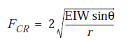
Dawson and Paslay developed the following formula for critical buckling
force in drill pipe.


where E is Young's modulus.
I is axial moment of inertia.
W is buoyed weight per unit length.
q is borehole inclination.
r is radial clearance between the pipe tool joint and the
borehole wall.
If the compressive load reaches the FCR, then sinusoidal buckling occurs.
This sinusoidal buckling formula can be used to develop graphs and tables
(see pages 4-18 through 4-23). If the compressive load at a given
inclination lies below the graph, then the drill pipe will not buckle. The
reason that pipe in an inclined hole is so resistant to buckling is that the
hole is supporting and constraining the pipe throughout its length. The low
side of the hole tends to form a trough that resists even a slight
displacement of the pipe from its initial straight configuration.
The graphs and tables provided in this section are for specific pipe/hole
configurations and may be used to look up the critical buckling force. The
following example illustrates how to calculate the critical buckling load.

Required BHA Weight For Rotary Assemblies

Required BHA Weight For Rotary Assemblies
When two contacting surfaces (i.e drillpipe and the borehole wall) are in
relative motion, the direction of the frictional sliding force on each surface
will act along a line of relative motion and in the opposite direction to its
motion. Therefore, when a BHA is rotated, most of the frictional forces
will act circumferentially to oppose rotation (torque), with only a small
component acting along the borehole (drag).
Measurements of downhole WOB by MWD tools has confirmed that when
the BHA is rotated there is only a small reduction in WOB due to drag.
This reduction is usually compensated for by using a “safety factor”.
Consider a short element of the BHA which has a weight “W” (see
following figure). Neglecting drag in the hole:
Effective weight in mud = W (BF)
Component of weight acting along borehole = W (BF) cosq
... where Q is the borehole inclination
Extending this discussion to the whole BHA,
WBIT = WBHA (BF) cosq
... where WBHA is the total air weight of the BHA and WBIT is the weight
on bit.
Therefore, if no drill pipe is to be run in compression

BHA Weight & Weight-On-Bit

BHA Weight & Weight-On-Bit

One important consideration in designing the BHA is determining the
number of drill collars and heavy-weight pipe required to provide the
desired weight-on-bit. When drilling vertical wells, standard practice is to
avoid putting ordinary drill pipe into compression (recommended by
Lubinski in 1950). This is achieved by making sure that the “buoyed
weight” of the drill collars and heavy-weight pipe exceed the maximum
weight-on-bit. This practice has also been adopted on low inclination,
directionally drilled wells.
In other types of directional wells, it must be remembered that since gravity
acts vertically, only the weight of the “along-hole” component of the BHA
elements will contribute to the weight-on-bit. The problem this creates is
that if high WOB is required when drilling a high inclination borehole, a
long (and expensive) BHA would be needed to prevent putting the drillpipe
into compression. However, for these high inclination wells, it is common
practice to use about the same BHA weight as used on low inclination
wells.
On highly deviated wells, operators have been running drillpipe in
compression for years. Analysis of drillpipe buckling in inclined wells, by
a number of researchers (most notably Dawson and Paslay), has shown that
drillpipe can tolerate significant levels of compression in small diameter,
high inclination boreholes. This is because of the support provided by the
“low-side” of the borehole.
Drillpipe is always run in compression in horizontal wells, without
apparently causing damage to the drillpipe.

Higher Grade Pipe In The Inclined Section Of The Well

Higher Grade Pipe In The Inclined Section Of The Well
The previous discussion was restricted to the simple case when the higher
grade pipe is totally in the vertical portion of the well. If the higher grade
pipe is used through a build-up section, the calculation becomes more
difficult. A rough approximation could be obtained by treating each stand
length as a straight section of hole and using the average inclination of that
course length. The weight this exerts along the borehole is found from:

Weight acting along borehole = weight of stand x cos (ave. inc.)

This, however, ignores drag which may be significant.
Similarly, for an inclined section of the well where the inclination is
constant, the weight acting along hole will be the air-weight of the pipe
multiplied by the cosine of the average inclination. Notice again that in this
particular calculation we do not use a buoyancy factor. This is because
although the entire drillstring is subject to a buoyancy force, that force is
acting on the lower portion of the string and affects the weight pulling
down on the top joint of lower grade pipe from below, but not the weight of
the joints of higher grade pipe at the top of the string.
It must be emphasized that if a higher grade pipe extends below the vertical
part of the well, then an accurate analysis of the axial stresses requires the
use of “Torque and Drag” programs.

Maximum Hookload When Two Grades Of Drill Pipe Are Used

Maximum Hookload When Two Grades Of Drill Pipe Are Used

When two grades of drill pipe are used, the higher grade (i.e. the pipe with
the higher load capacity) is placed above the lower grade pipe. The
maximum tension to which the top joint can be subjected is based on the
yield strength of the higher grade of pipe. Calculations similar to those
already dealt with may be used to determine the maximum length of both
grades of pipe.
Another consideration is the maximum hookload which can be applied
when only a few stands of the higher grade pipe have been added. Provided
the higher grade pipe is in the vertical section, maximum hookload (pickup
load) is calculated as the yield strength of the lower grade of pipe PLUS
the “air weight” of the higher grade pipe. This is because the surface
hookload includes the weight of the higher grade pipe; but that weight
(since it is supported from the surface) does not act on the top joint of
lower grade pipe.
Maximum Hookload = Yield Strength + Weight
Of Lower Grade Pipe Of Higher Grade Pipe
When a sufficient length of higher grade pipe has been added, the limiting
condition will become the yield strength of the higher grade pipe.
The air weight of the higher grade pipe is used because the buoy force
acting on the drillstring is acting on the bit and components of the BHA.
The hydrostatic pressure which the mud exerts on the drill pipe in the upper
(vertical) section of the hole does not create a resultant force acting
upwards.

Buoyancy & Hookload - Overpull

Overpull

In tight holes or stuck pipe situations, the operator must know how much
additional tension, or pull, can be applied to the string before exceeding the
yield strength of the drill pipe. This is known as Overpull, since it is the
pull force over the weight of the string. For example, in a vertical hole with
12 ppg mud, a drillstring consists of 600 feet of 7.25-inch x 2.25-inch drill
collars and 6,000 ft of 5-inch, New Grade E drill pipe with a nominal
weight of 19.5 lbs/ft and an approximate weight of 20.89 lbs/ft.
First, the hookload is determined
Hookload = Air Weight x Buoyancy Factor
= [(6,000 x 20.89) + (600 x 127)] 0.817
= 164,658 pounds
Referring to the API RP 7G, the yield strength in pounds for this grade,
class, size and nominal weight of drill pipe is 395,595 pounds. Therefore:
Maximum Overpull = Yield Strength In Pounds - Hookload
= 395,595 - 164,658
= 230,937 pounds
The operator can pull 230,937 pounds over the hookload before reaching
the limit of elastic deformation (yield strength). Obviously, as depth
increases, hookload increases, at a certain depth the hookload will equal
the yield strength (in pounds) for the drill pipe in use. This depth can be
thought of as the maximum depth that can be reached without causing
permanent elongation of the drill pipe (disregarding hole drag as a
consideration). Practically, an operator would never intend to reach this
limit. A considerable safety factor is always included to allow for overpull
caused by expected hole drag, tight hole conditions or a stuck drillstring.
In practice, selection of the drill pipe grade is based upon predicted values
of pick-up load. For a directional well, the prediction of pick-up load is
best obtained using a Torque and Drag program, as well as including the
capacity for overpull. Some operators include an additional safety factor by
basing their calculations on 90% of the yield strength values quoted in API
RP7G.

Buoyancy & Hookload - Introduction

Buoyancy & Hookload

Introduction

Drillstrings weigh less in weighted fluids than in air due to a fluid property
known as buoyancy. Therefore, what is seen as the hookload is actually the
buoyed weight of the drillstring. Archimedes’s principle states that the
buoy force is equal to the weight of the fluid displaced. Another way of
saying this is that a buoy force is equal to the pressure at the bottom of the
string multiplied by the cross sectional area of the tubular. This is due to
the fact that the force of buoyancy is not a body force such as gravity, but a
surface force.
For example, the buoy force exerted on 7.5-inch x 2-inch drill collars in a
700 ft vertical hole with 12 ppg mud would be 17,925 pounds.
Buoy Force = Pressure x Area
Hydrostatic Pressure = 0.0519 x MW x TVD
= 0.0519 x (12) x (700)
= 436.8 psi
Cross Sectional Area = p/4 x (OD2 - ID2)
= p/4 x (7.52 - 22)
= p/4 x (56.25 - 4)
= 41.04 in2
Buoy Force = 436.8 x 41.04
= 17,924.99 pounds
By looking at the API RP 7G it can be determined that the air weight of
these 7.5-inch drill collars is 139 pounds per foot. If we have 700 feet of
collars, the total air weight would be 97,300 pounds.
Total Air Weight = weight per foot x length
= 139 x 700
= 97,300 pounds
The buoyed weight of the collars, or the Hookload, is equal to the air
weight minus the buoy force.
Hookload = Air Weight - Buoy Force
= 97,300- 17,925
= 79,375 pounds
This method for determining the buoyed weight is not normally used.
Instead, the following formula, which incorporates a buoyancy factor, is
used and recommended by the API.
MW=Mud Density (ppg)
Hookload = Air Weight x Buoyancy Factor
= 97,300 x 0.817
= 79,494 pounds
Buoyancy Factors rounded off to three places can also be found in the API
RP 7G (Table 2.13).
Note: The formula above for hookload does not take into
account axial drag. Hookload, as determined in the
formula above is the approximate static surface hookload
that would be displayed by the weight indicator in a
vertical hole with no drag, excluding the weight of the
traveling block, drill line etc.
In practice, hookload will vary due to motion and hole drag. Pick-Up Load
refers to the hookload when pulling the drillstring upwards. The highest
hookload normally encountered will be when attempting to pick up the
string. Slack-Off Load refers to the hookload when lowering the drillstring.
Drag Load refers to the hookload when drilling in the oriented mode. Other
references to hookload are Rotating Off-Bottom Load and (rotary) Drilling
Load.