Swab And Surge Pressures
Both swab and surge pressures are caused by moving the drillstring axially, and can be calculated using a method similar for calculating annular pressure losses. The greatest difficulty is determining the fluid flow velocity in the annulus when the pipe is opened-ended, because the
distribution of flow between the drillstring and annulus cannot be determined by a simple method.
Two approaches have been proposed.
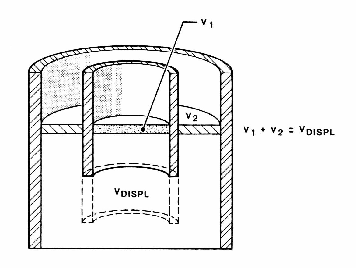
The first assumes that fluid levels in the annulus and drillstring remain equal at all times. Annular fluid velocity then becomes:

where: Va = Average velocity (ft/min)
Vp = Drillstring velocity (ft/min)
D = Borehole Diameter (inches)
d = Drillstring Outside Diameter (inches)
di = Drillstring Inside Diameter (inches)
The minus sign is in the equation because the drillstring velocity is in the opposite direction to the fluid velocity.
This average velocity equation remains valid even when hole geometry changes. This method is easy to apply and is in widespread use in the oilfield. Its basic premise, that fluid levels in the drillstring and annulus
remain equal, is rarely justified. Because of the greater restrictions to flow, caused by the bit nozzles and pipe bore, actual flow in the annulus will nearly always exceed that calculated by this method. Calculated swab and surge pressures are therefore usually too low.
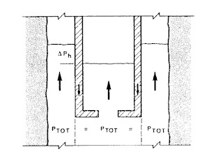
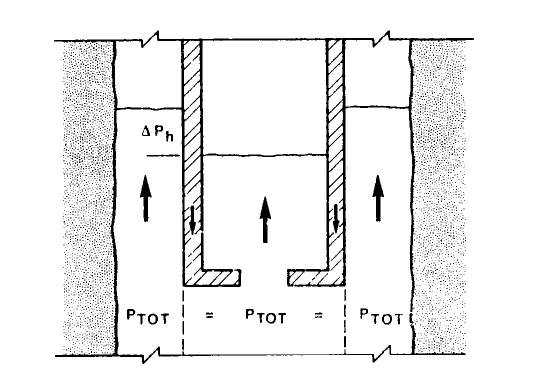
An alternative procedure considers the drillstring and the annulus as a “UTube”, as shown in the following figure.
It is clear that the sum of hydrostatic and frictional pressures in the pipe bore and through the bit should equal the sum of hydrostatic and frictional pressures in the annulus. Both sums represent the pressure prevailing immediately below the bit.
There is only one flow distribution that will fulfill this criterion, and it can
be found by trial and error through the use of the pressure loss equations.
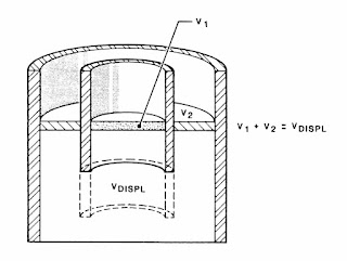
Figure 1-3: Equal Level Displacement
When tripping out of the hole, it may be assumed that both drillstring and annulus are kept full of fluid. The required distribution of flow is that which gives equal frictional losses in the pipe bore and annulus. When tripping into the hole, the fluid level inside the drillstring can drop well below that in the annulus, if small bit nozzles are present. This effect is usually seen as a pit volume being higher than expected, string weight lower than expected, and a considerable volume being pumped before standpipe pressure builds up while breaking circulation.
When the fluid level in the drillstring is below that of the annulus, a greater hydrostatic pressure will exist in the annulus, and fluid will tend to flow from the annulus up the drillstring. In this case, calculating flow distribution by equating frictional losses gives a calculated annular flow and surge pressure slightly higher than actually exists. Because this error is small and conservative, and because at present there is no reliable way of measuring the fluid level within the pipe, the practice of calculating flow distribution by equating internal and external pressure losses is generally accepted.
If the pipe is closed, or contains a float sub, it is easy to calculate flow in the annulus, because all of the fluid displaced by the drillstring passes up the annulus.

Calculating the pressure drop in the annulus is complicated by the motion of the inner wall of the drillstring. This motion is in the opposite direction to the displaced fluid, so the pressure drop will be greater than that for the same flowrate in a stationary annulus . Equations describing the system can be formulated, but solutions are usually too complicated for wellsite use.
Figure