Showing posts with label drilling. Show all posts

Thursday, 11 February 2016

Nudging

Nudging
The technique of “nudging” is used on platforms in order to “spread out”
conductors and surface casings, which minimizes the chance of a collision.
Basically, when the hole for surface casing is drilled, some angle is built at
a low rate (e.g. 1°/100') in the chosen direction.
In addition to “spreading things out”, other reasons for “nudging” are:
• to drill from a slot located on the opposite side of the platform from
the target, when there are other wells in between
• to keep wells drilled in the same general direction as far apart as
possible
• if the required horizontal displacement of a well is large compared to
the total vertical depth, then it is necessary to build angle right below
the surface conductor to avoid having to use a high build rate

Tuesday, 9 February 2016

Planning The Well Trajectory - Horizontal wells and Allocation of slots to targets

Horizontal wells
For many applications, the best well profile is one in which the inclination
is built to 90° or even higher.

Allocation of slots to targets
Even this is not always a simple task. From a directional driller's
viewpoint, slots on the North East side of the platform or pad should be
used for wells whose targets are in a North Easterly direction.
Unfortunately there are other considerations (e.g. water injection wells
may have to be grouped together for manifolding requirements). Also, as
more wells are drilled and the reservoir model is upgraded, targets can be
changed or modified.
Inner slots are used to drill to the innermost targets (i.e. targets with the
smallest horizontal distances from the platform) and these wells will be
given slightly deeper kick-off points. The outer slots are used to drill to
targets which are furthest from the platform. These wells will be given
shallow kick-off points and higher build-up rates to keep the maximum
inclination as low as possible.

Wednesday, 3 February 2016

Fault Drilling

Fault Drilling

Directional wells are also drilled to avoid drilling a vertical well through a
steeply inclined fault plane which could slip and shear the casing.


Inaccessible locations

Inaccessible locations


Directional wells are often drilled because the surface location directly
above the reservoir is inaccessible, either because of natural or man-made
obstacles.


Sidetracking

Sidetracking


Sidetracking out of an existing wellbore is another application of
directional drilling. This is done to bypass an obstruction (“fish”) in the
original wellbore, to explore the extent of a producing zone in a certain
sector of a field, or to sidetrack a dry hole to a more promising target.
Wells are also sidetracked to access more reservoir by drilling a horizontal
hole section from the existing well bore.


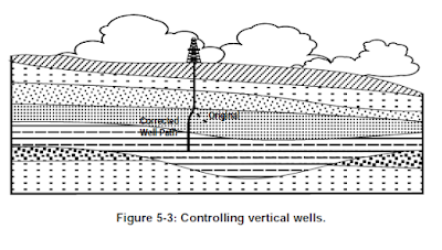
Controlling Vertical Wells

Controlling Vertical Wells

Directional techniques are used to “straighten crooked holes”. When
deviation occurs in a well which is supposed to be vertical, various
techniques can be used to bring the well back to vertical. This was one of
the earliest applications of directional drilling.


Relief Wells

Relief Wells

Directional techniques are used to drill relief wells in order to “kill”
blowouts. Relief wells are deviated to pass as close as possible to the
uncontrolled well. Heavy mud is pumped into the reservoir to overcome
the pressure and bring the wild well under control.

Definition of Directional Drilling

Definition of Directional Drilling

Directional drilling can generally be defined as the science of directing a
wellbore along a predetermined trajectory to intersect a designated subsurface
target.

Friday, 29 January 2016

Removal of the Drilling Fluid

Removal of the Drilling Fluid
For cementing operations to be successful, all annular spaces must be filled with cement, and the cement properly bonded to the previous casing and formation. In order for this to occur, all the drilling fluid must be displaced by the cement slurry. This is not always an easy matter, because there are several factors which affect the removal of the drilling fluid:

• washouts in the open hole, making it difficult to remove drilling fluid and filter cake
• crooked holes, making casing centralization difficult and drilling fluid not being removed from the low side
• poorly treated drilling fluids having high fluid losses Good drilling practices will not assure a good cement job, but they may help prevent a failure. The ideal drilling fluid for cementing operations should have:

• a low gel strength, with low PV and low YP
• a low density
• a low fluid loss
• a chemical make-up similar to the cement

Since these conditions are very seldom met, fluid washes and spacers are usually pumped ahead of the cement to remove as much drilling fluid as possible.

Wednesday, 27 January 2016

Cuttings Slip Velocity

Cuttings Slip Velocity

A cutting, traveling up the annulus, experiences a positive upward force due to the drilling fluid velocity, density and viscosity, and a negative downward force due to gravity. The rate at which a cutting falls is known as its “slip velocity”.

Several studies have enabled the following generalizations to be made:

1. The most important factors controlling adequate cuttings transport are annular velocity and rheological properties

2. Annular velocities of 50 ft/min provide adequate cuttings transport in typical muds

3. Cuttings transport efficiency increases as fluid velocity increases

4. The slippage of cuttings as they are transported induces shear thinning of the mud around the cutting reducing the expected transport efficiency

5. Cutting size and mud density have a moderate influence on cuttings transport

6. Hole size, string rpm, and drill rate have slight effects on cuttings transport.

Those who have observed a solids tracer emerging over the shale shaker will realize the large spread of “cuttings” that occurs. Therefore, any calculated estimation of slip velocity will only be an approximation. The reason for this “spread” of solids is the particles ability to be carried by the drilling fluid. It is a function of its position in the mud stream and the size of the particle. Cuttings will travel up the annulus more efficiently if they travel flat and horizontally. If the cutting turns on its edge, it will slip more easily. Smaller cuttings are more prone to do this. Rotation of the drillpipe will result in a helical motion of the fluid, which will aid transport for those
cuttings nearest the pipe.

The rheological properties of the drilling fluid will affect cuttings transport, in as much as they affect the flow profile. Lowering the “n” value or an increases in the YP/PV ratio will generally flatten the flow profile and increase carrying capacity.

The slip velocity of a cutting in turbulent flow may be estimated using:

where: Vs = Slip Velocity (ft/min)
dp = Particle Diameter (inches)
pp = Particle density (lb/gal)
MD = Mud Density (lb/gal)
CD = Drag Coefficient

For these calculations, the particle density is found by multiplying the cuttings density (gm/cc) by the density of fresh water (8.34). The drag coefficient is the frictional drag between the fluid and the particle.

In turbulent flow, the drag coefficient is 1.5.
In laminar flow, the equivalent viscosity (m) will effect the slip velocity. In this case the slip velocity is

:
Equivalent viscosity is calculated as mentioned earlier.

Cuttings Transport

Cuttings Transport

One of the primary functions of a drilling fluid is to bring the drilled cuttings to the surface. Inadequate hole cleaning can lead to a number of problems, including hole fill, packing off, stuck pipe, and excessive hydrostatic pressure. The ability of a drilling fluid to lift cuttings is affected by many factors, and there is no universally accepted theory which can account for all observed phenomena. Some of the parameters which affect cuttings transport are the fluids density and viscosity, annular size and eccentricity, annular velocity and flow regime, pipe rotation, cuttings density, and the size and shape of the cuttings.

If the cuttings are of irregular shape (and most are) they are subjected to a torque caused by the shearing of the mud. If the drillpipe is rotating, a centrifugal effect causes the cuttings to move towards the outer wall of the annulus. The process is further complicated because the viscosity of non- Newtonian fluids varies according to the shear rate, and therefore the velocity of the cutting changes with radial position. Finally, transport rates are strongly dependent on cutting size and shape, which as stated above, are both irregular and variable.

The only practical way to estimate the slip velocity (or relative sinking velocity) of cuttings, is to develop empirical correlations based on experimental data. Even with this approach, there is a wide disparity in the results obtained by different authors.

Reynolds Number and Critical Velocity

Reynolds Number and Critical Velocity

The Reynolds Number, used in the annular Power Law Model calculations is calculated using equivalent viscosity


:

Reynolds Number is then:


The fluid velocity that will produce the critical Reynolds Number for given fluid properties and pipe configuration is found using:


where: ReL = Laminar/Transitional Reynolds Number
(3470-1370n).

Drillstring Pressure Losses

Drillstring Pressure Losses

All pressure losses, at first, assume a laminar flow regime. Power Law Model calculations begin with:


where: Plf = Pressure Loss in Laminar Flow (psi)

L = Length of Section (feet)
VP = Velocity in Section of drill string (ft/min)
d = Inside Diameter of drillstring (inches)
k = Consistency Index
n = Power Index
Fluid velocity in the drillstring can be determined by using:


where: Q = Pump flow rate (gpm)
d1 = pipe I.D. (inches)
The equivalent viscosity (m) is then determined, using:


Which, in turn, is used to determine the Reynolds Number.
Flow behavior, with the Power Law Model, will vary depending on the “n” value of the fluid. The critical Reynolds Number (Rec) is found using: 3470 - 1370n (from laminar to transitional)
4270 - 1370n (from transitional to turbulent)

If: Re < Rec flow is laminar
Re is between laminar and turbulent, flow is transitional
Re > Rec flow is turbulent
If the flow is determined to be turbulent, the pressure losses will have to be re-calculated using turbulent flow. This will also require a friction factor (f) to be included: