Showing posts with label well planning. Show all posts

Friday, 19 February 2016

Downhole Motors - Turbines- Turbine Characteristics

Turbine Characteristics
• Torque and RPM are inversely proportional (i.e. as RPM increases,
torque decreases and vice versa).
• RPM is directly proportional to flow rate (at a constant torque).
• Torque is a function of flow rate, mud density, blade angle and the
number of stages, and varies if weight-on-bit varies.
• Optimum power output takes place when thrust bearings are balanced.
• Changing the flow rate causes the characteristic curve to shift.
• Off bottom, the turbine RPM will reach “run away speed” and torque
is zero.
• On bottom, and just at stall, the turbine achieves maximum torque and
RPM is zero.
• Optimum performance is at half the stall torque and at half the
runaway speed, the turbine then achieves maximum horsepower.
• A stabilized turbine used in tangent sections will normally cause the
hole to “walk” to the left.
Downhole Motors - Turbines- Turbine Observations

Turbine Observations
• There is minimal surface indication of a turbine stalling.
• Turbines do not readily allow the pumping of LCM.
• Sand content of the drilling fluid should be kept to a minimum.
• Due to minimal rubber components, the turbine is able to operate in
high temperature wells.
• Pressure drop through the tool is typically high and can be anything
from 500 psi to over 2000 psi.
• Turbines do not require a by-pass valve.
• Usually, the maximum allowable bearing wear is of the order of 4mm.

Downhole Motors - Turbines- Directional Turbine

Directional Turbine
This is a short tool which has a set number of stages and its bearing section
entirely within one housing. That is, it is not a sectional tool and will be
typically less than 30 feet long. It is designed for short runs to kick off or
correct a directional well, using a bent sub as the deflection device.
Steerable turbodrills do exist and will be discussed later.

Downhole Motors - Turbines- Bearing Section

Bearing Section
Usually, thrust bearings are made up of rubber discs (Figure 5-24) which
are non-rotating (being fixed to the outer housing of the tool) and rotating
steel discs attached to the central rotating shaft. Long bearing sections
known as cartridges are used for long life in tangent or straight hole drilling
sections. These are changeable at the rigsite. If the bearings wear past the
maximum point, considerable damage can be inflicted as the steel rotors
will crash into the stators below.

Downhole Motors - Turbines- Drive Section

Drive Section
This will consist of a series of bladed stators, fixed to the outer tool housing
and bladed rotors fixed to the central rotating shaft. Mud flow is deflected
at a pre-determined angle off the stator blades to hit the rotor blades and
cause the shaft to rotate. The angle of the blades will affect the torque and
speed output of the turbine

Wednesday, 17 February 2016

Downhole Motors - Turbines

Turbines
A turbine is made up of several sections:
• Drive stages or motor section.
• Axial thrust bearing assembly and radial bearings.
• Bit drive sub.
As stated earlier, the drive stages, or motor section, consists of a series of
stators and rotors of a bladed design. This stator and rotor combination
form a stage. Turbines are referred to as 90 stage, 250 stage, etc. The
number of stages determines the torque generated. Each stage,
theoretically, applies an equal amount of torque to the control shaft and it is
the sum of those torques which will be output to the bit.
The drive sub is simply the bit connection and bearing shaft. Radial
bearings protect the shaft from lateral loading and the thrust bearings
support the downwards hydraulic thrust from mud being pumped through
the tool and the upward thrust of weight being applied to the bit.
Theoretically, weight on bit should be applied to equalize the hydraulic
thrust, which unloads the bearings and prolongs their life.

Tuesday, 16 February 2016

Downhole Motors - Positive Displacement Motors : Motor Orientation/Control

Motor Orientation/Control
All directional wells require steering during initial kick offs, correction
runs, sidetracks, and re-drills. Once the desired direction in which the tool
should be faced is determined, the next step is to actually face the tool in
that direction in order to drill the predetermined course.
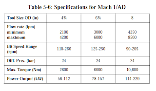
For the Mach 1/AD motor, a cartridge data transmission (CDT) system has
been developed that allows orientation of the motor in a particular
direction, while still allowing drilling with drillstring rotation. This CDT
system uses a special heavy duty steering tool which provides continuous
surface readout of the drift angle and azimuth, as well as toolface
orientation while drilling ahead.
A “hard wire” from the steering tool, through the drillstring to the surface,
relays the information to computerized surface equipment. Data
transmitted from the steering tool is updated and converted instantly to
information which can be used to make any necessary corrections to the
motor.


Downhole Motors - Positive Displacement Motors :Navi-Drill Mach 1/AD

Navi-Drill Mach 1/AD
The Navi-Drill Mach 1/AD motor is designed specifically for use in holes
drilled with air and mist. With an AKO, the steerable motor drilling system
combines directional and straight hole drilling capabilities to provide
precise directional control. Generally, in one run it can establish the desired
direction and inclination for the surface interval of a directional well.
The AKO places the bend close to the bit, and can be adjusted so the motor
housing tilt angle can be configured on the rig floor to settings from 0° -
2.5°. The resulting dogleg capability can be as high as 12°/100 ft. The
unique AKO design requires no shims to adjust the bent housing angle, so a
single motor can achieve a variety of build rates.
This motor, with the AKO, can perform directional work when oriented in
a particular direction, and is capable of drilling straight ahead when the
drillstring is rotating. This is accomplished by tilting the bit relative to the
motor and/or applying a side force at the bit while maintaining a minimum
amount of bit offset relative to the axis of the motor.
When an alignment bent sub (ABS) is fitted to the top of the motor and
used in conjunction with the AKO, the motor configuration can be used for
building angle, as in a fixed angle build motor. Orientation of the motor
and drillstring is possible in this configuration, but not rotation. The
maximum build rate possible from this configuration is approximately 20°/
100 ft.

Saturday, 13 February 2016

Downhole Motors - Positive Displacement Motors : Navi-Drill Mach 1 P/HF

Navi-Drill Mach 1 P/HF
The Navi-Drill Mach 1 P/HF (High Torque/High Flow) is a positive
displacement motor that develops high torque at the bit at relatively low to
medium speed range (80-310 RPM). This makes it ideal for directional
applications, drilling with high weight-on-bit, or in areas where formations
require high torque due to specialized PDC bits.
The Navi-Drill Mach 1 P/HF motor has a multi-lobe rotor/stator
configuration which generates more torque than other motors.
A unique bearing assembly and improved elastomer compounds have
increased the Mach 1 P/HF’s hydraulic horsepower and extended its
operating life. The rotor/stator design allows a larger than normal flow rate
to be pumped through the motor, generating the higher torques. There is a
rotor nozzling system that allows the motor to run over the higher
maximum flow rate without exceeding maximum recommended motor
speed. These higher flow rates offer improved hole cleaning and bit
hydraulics.
The Navi-Drill Mach 1 P/HF offers the AKO (adjustable kick off sub)
which is rig floor adjustable between 0° - 2.75°, giving a BUR up to
12°/100 ft. Included in the design is a unique U-joint assembly which
allows the higher torque to be transmitted from the motor section through
the bearing assembly and to the bit.
Although primarily a directional performance drilling motor, the Navi-
Drill Mach 1 P/HF can also be used for straight-hole drilling.

Downhole Motors - Positive Displacement Motors : Navi-Drill Mach 2

Navi-Drill Mach 2
The Navi-Drill Mach 2 is a positive-displacement motor that can improve
drill rates in both straight-hole and directional applications.
The Mach 2 has a multi-stage, 1/2 rotor/stator configuration, which
generates low to medium torque at medium speeds for higher penetration
rates with less weight-on-bit. This makes it a good choice for drilling
straight and directional holes in difficult formations. The motor is
particularly suited for long-interval performance drilling with natural
diamond, TSP, or PDC bits.
Mach 2 motors also come in 1-3/4”, 2-5/8” and 4-3/4” ODs for slimhole
applications.
Tables 5-3 and 5-4 list the Mach 2 specifications.


Downhole Motors - Positive Displacement Motors : Navi-Drill Mach 1C

Navi-Drill Mach 1C
The Mach 1C is a positive-displacement motor that develops high torque at
the bit at relatively low speed ranges (80-340 rpm). This makes it ideal for
directional applications, drilling with high weight-on-bit, navigation
drilling with roller cone or large cutter PDC bits, and coring operations.
The motor has a multi-lobe (5/6) rotor/stator configuration, which
generates higher torque than the 1/2 lobe motors, permitting more weighton-
bit and increasing the drill rate. Because the motor develops its power at
low speeds, it can improve bit performance without accelerating wear on
the bearings or cones.
A unique bearing assembly and improved elastomer compounds in the
stator have increased the Mach 1C’s hydraulic horsepower and extended
operating life. It also has a new rotor nozzling system that allows the motor
to be run at 50-100% over its maximum recommended flow rate without
exceeding maximum recommended motor speed. The additional mud
passes through the motor’s rotor, and flow rate can be adjusted by
interchanging nozzles. Higher rates offer improved hole cleaning and bit
hydraulics.
Although primarily a directional performance drilling motor, the Mach 1C
can also be used for straight-hole drilling.
Tables 5-1 and 5-2 detail the Mach 1C specifications.


Downhole Motors - Positive Displacement Motors : Characteristics

Characteristics
• Torque is directly proportional to the motor’s differential pressure.
This makes the tool a very simple to operate.
• RPM is directly proportional to flow rate, through somewhat affected
by torque output.
• Hydraulic horsepower consumed = {(P x Q) ¸ 1714}, where P is the
pressure drop (psi) across the motor and Q is flow rate (gpm).

Downhole Motors - Positive Displacement Motors : PDM Observations

PDM Observations
• Motor stall will be obvious due to an increase in surface pressure.
Motor stalling should be avoided as it erodes the service life of the
motor.
• LCM can be pumped safely, though care should be taken that the
material is added slowly and evenly dispersed. The system should not
be slugged.
• Sand content in the drilling fluid should be kept to a minimum.
• Temperature limits are around 270°F to 130ºC, but higher temperature
stators have been developed.
• Pressure drop through the tool while working is typically around 50
psi to 800 psi.
• Allowable wear on bearings is of the order of 1mm - 8mm, depending
upon tool size.
• The tool should be flushed out with water prior to laying down.
In general, drilling fluids with a low aniline point can damage the rubber
stator. As a rule, the nailine point in oil based muds should be around
150°F (60°C). Usually, this is related to the aromatic content which should
be equal to or less than 10%. Contact the local supplier if there is any
doubt.
If a by-pass nozzle is fitted to a multi-lobe rotor, then it must be sized very
carefully to allow the motor section to develop the necessary power. Any
variation in flow for which the nozzle was inserted will compromise the
motor’s performance.

Downhole Motors - Positive Displacement Motors : Types of Positive Displacement Motors

Types of Positive Displacement Motors
PDMs come in various configurations. As has been mentioned previously,
the stator will have one more lobe than the rotor. The first types of PDMs,
and the simplest, are 1/2 motors. These generally give medium to low
torque output and medium to high rotary speed. Torque output is directly
proportional to pressure drop across the motor. The
1/2 motors have good applications in performance drilling with a PDC,
diamond, or TSP-type bits. Some shorter models are used for directional
purposes.

Multi-lobe motors have high torque output and relatively slow speed.
Therefore, they have good applications with roller cone bits and for coring.
Such motors are also suitable for use with PDC bits, especially the large
cutter types which require a good torque output to be efficient. These tools,
being fairly short, also have good directional applications with bent subs as
the deflection device. Multi-lobe motors may be constructed with a hollow
rotor and a nozzle or blank placed in a holding device at the top. The nozzle
allows for high flow rates to be accommodated by by-passing the excess
flow from the motor section and the fluid will exit through the bit.

Downhole Motors - Positive Displacement Motors : Bearing Section

Bearing Section
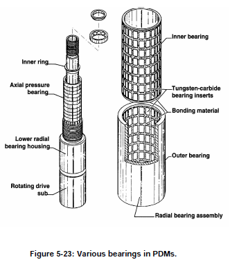
A typical positive displacement motor utilizes three sets of bearings
attached to a drive shaft. There are two sets of radial bearings (“upper” and
“lower”) with one set of axial thrust bearings.
The axial thrust bearing section supports the on and off bottom loading and
hydraulic thrust. It consists of a series of ball bearings stacked one on top
of the other, each set being contained in its own race (groove). The number
of these bearings will vary, depending on the size of the tool.

The upper and lower radial bearings are lined with tungsten carbide inserts.
These bearings support the concentrically rotating drive shaft against
lateral loads. The inherent design of the upper radial bearing limits the
amount of fluid flow diverted to cool and lubricate the bearing package.
This diversion of flow is typically 2 - 10%, depending on motor and bit
pressure drop. The major portion of the drilling fluid is collected by ports
in the drive shaft and exits through the bit. In some motors, diamond
bearings are used, which need up to 20% of the flow to be diverted,
depending upon conditions. Figure 5-23 illustrates typical bearing sections
found in PDMs.


Friday, 12 February 2016

Downhole Motors - Positive Displacement Motors : Connecting rod assemblies

Connecting rod assemblies
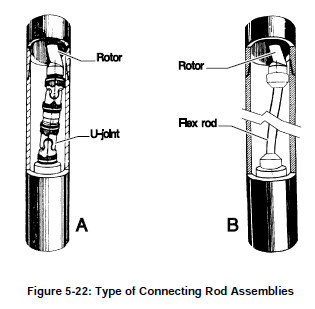
Since the rotor is spiral shaped, it does not rotate concentrically, rather it
traces a back and forth motion. This motion must be converted to a
concentric motion to be transmitted to the bit via the drive sub. This is
achieved by a connecting rod assembly. There are several types.
Universal-joint
U-joint assemblies (Figure 5-22a) have been utilized by the industry and
are still used in most positive displacement motors. The assembly consists
of two universal joints, each grease filled, and sealed with oil-resistant
reinforced rubber sleeves to protect them from drill fluid contamination. A
drawback of the U-joint assembly is the lack of sufficient strength for
higher torque applications, such as those encountered with recent
generations of high torque PDM’s, particularly when used with PDC bits.
This inherent weakness is a result of the manufacturing process whereby
the U-joint is “flame-cut” rather than machined.
Flex rod
A recent development in connecting rod assembly technology has been the
utilization of flexible steel or titanium “flex rods” (Figure 5-22b). While
flex rods are limited by the degree of allowable lateral bending, they have
the advantage of low maintenance, since they do not require lubricants or
rubber sleeves. Flex rods are now standard on most smaller Navi-Drills.
One recent approach has been to mount the flex rod inside the hollow rotor
of a short, high torque steerable PDM, rather than connecting it to the
bottom of the rotor. By connecting a long flex rod to the inside of the top
end of the rotor and extending it through the rotor, to connect to the top of
the drive sub assembly, the overall rate of bend is decreased due to its
increased length.


Downhole Motors - Positive Displacement Motors : Motor Section

Motor Section
This is a reverse application of Rene Moineau’s pump principle. The motor
section consists of a rubber stator and steel rotor. The simple type is a
helical rotor which is continuous and round. This is the single lobe type.
The stator is molded inside the outer steel housing and is an elastometer
compound. The stator will always have one more lobe than the rotor.
Hence motors will be described as 1/2, 3/4, 5/6 or 9/10 motors.
Both rotor and stator have certain pitch lengths and the ratio of the pitch
length is equal to the ratio of the number of lobes on the rotor to the
number of lobes on the stator.
As mud is pumped through the motor, it fills the cavities between the
dissimilar shapes of the rotor and stator. The rotor is forced to give way by
turning or, in other words, is displaced (hence the name). It is the rotation
of the rotor shaft which is eventually transmitted to the bit.

Downhole Motors - Positive Displacement Motors : By-Pass Valve


By-Pass Valve

The by-pass valve allows fluid to fill the drill string while tripping in the
hole and to drain while tripping out. When mud is pumped, the valve closes
causing fluid to move through the tool. Most valves are of a spring piston
type which closes under pressure to seal off ports to the annulus. When
there is no downward pressure, the spring forces the piston up so fluid can
channel through the ports to the annulus. (Figure 5-20).

Thursday, 11 February 2016

Proximity (anti-collision) analysis

Proximity (anti-collision) analysis
On multi-well projects (particularly offshore) there are small distances
between slots. To eliminate the risk of collisions directly beneath the
platform, the proposed well path is compared to existing and other
proposed wells. The distances between the other wells and the proposal are
calculated at frequent intervals in critical sections. These calculations can
be performed using the EC*TRAK software (BHI) or COMPASS.
Survey uncertainty must also be computed for both the proposed well and
the existing wells. All major operating companies have established criteria
for the minimum acceptable separation of wells, which are usually linked
to “cone of error” or “ellipse of uncertainty” calculations.

Nudging - Planning a nudge program

Planning a nudge program
The directions in which the wells are “nudged'' should be chosen to achieve
maximum separation. Wells may not necessarily be nudged in their target
directions.
Nudges will not only be shown on the individual well plans for each well,
but a structure plot will also be drawn which will show well positions at the
surface casing point after the nudge.