Sunday, 9 October 2016
Enhanced oil recovery
Enhanced oil recovery (abbreviated EOR) is the implementation of various techniques for increasing the amount of crude oil that can be extracted from an oil field. Enhanced oil recovery is also called improved oil recovery or tertiary recovery (as opposed to primary and secondary recovery).
Friday, 19 February 2016
Downhole Motors - Turbines- Turbine Characteristics
Turbine Characteristics
• Torque and RPM are inversely proportional (i.e. as RPM increases,
torque decreases and vice versa).
• RPM is directly proportional to flow rate (at a constant torque).
• Torque is a function of flow rate, mud density, blade angle and the
number of stages, and varies if weight-on-bit varies.
• Optimum power output takes place when thrust bearings are balanced.
• Changing the flow rate causes the characteristic curve to shift.
• Off bottom, the turbine RPM will reach “run away speed” and torque
is zero.
• On bottom, and just at stall, the turbine achieves maximum torque and
RPM is zero.
• Optimum performance is at half the stall torque and at half the
runaway speed, the turbine then achieves maximum horsepower.
• A stabilized turbine used in tangent sections will normally cause the
hole to “walk” to the left.
Downhole Motors - Turbines- Turbine Observations
Turbine Observations
• There is minimal surface indication of a turbine stalling.
• Turbines do not readily allow the pumping of LCM.
• Sand content of the drilling fluid should be kept to a minimum.
• Due to minimal rubber components, the turbine is able to operate in
high temperature wells.
• Pressure drop through the tool is typically high and can be anything
from 500 psi to over 2000 psi.
• Turbines do not require a by-pass valve.
• Usually, the maximum allowable bearing wear is of the order of 4mm.
Downhole Motors - Turbines- Directional Turbine
Directional Turbine
This is a short tool which has a set number of stages and its bearing section
entirely within one housing. That is, it is not a sectional tool and will be
typically less than 30 feet long. It is designed for short runs to kick off or
correct a directional well, using a bent sub as the deflection device.
Steerable turbodrills do exist and will be discussed later.
Downhole Motors - Turbines- Bearing Section
Bearing Section
Usually, thrust bearings are made up of rubber discs (Figure 5-24) which
are non-rotating (being fixed to the outer housing of the tool) and rotating
steel discs attached to the central rotating shaft. Long bearing sections
known as cartridges are used for long life in tangent or straight hole drilling
sections. These are changeable at the rigsite. If the bearings wear past the
maximum point, considerable damage can be inflicted as the steel rotors
will crash into the stators below.
Downhole Motors - Turbines- Drive Section
Drive Section
This will consist of a series of bladed stators, fixed to the outer tool housing
and bladed rotors fixed to the central rotating shaft. Mud flow is deflected
at a pre-determined angle off the stator blades to hit the rotor blades and
cause the shaft to rotate. The angle of the blades will affect the torque and
speed output of the turbine
Wednesday, 17 February 2016
Downhole Motors - Turbines
Turbines
A turbine is made up of several sections:
• Drive stages or motor section.
• Axial thrust bearing assembly and radial bearings.
• Bit drive sub.
As stated earlier, the drive stages, or motor section, consists of a series of
stators and rotors of a bladed design. This stator and rotor combination
form a stage. Turbines are referred to as 90 stage, 250 stage, etc. The
number of stages determines the torque generated. Each stage,
theoretically, applies an equal amount of torque to the control shaft and it is
the sum of those torques which will be output to the bit.
The drive sub is simply the bit connection and bearing shaft. Radial
bearings protect the shaft from lateral loading and the thrust bearings
support the downwards hydraulic thrust from mud being pumped through
the tool and the upward thrust of weight being applied to the bit.
Theoretically, weight on bit should be applied to equalize the hydraulic
thrust, which unloads the bearings and prolongs their life.
Tuesday, 16 February 2016
Downhole Motors - Positive Displacement Motors : Motor Orientation/Control
Motor Orientation/Control
All directional wells require steering during initial kick offs, correction
runs, sidetracks, and re-drills. Once the desired direction in which the tool
should be faced is determined, the next step is to actually face the tool in
that direction in order to drill the predetermined course.
For the Mach 1/AD motor, a cartridge data transmission (CDT) system has
been developed that allows orientation of the motor in a particular
direction, while still allowing drilling with drillstring rotation. This CDT
system uses a special heavy duty steering tool which provides continuous
surface readout of the drift angle and azimuth, as well as toolface
orientation while drilling ahead.
A “hard wire” from the steering tool, through the drillstring to the surface,
relays the information to computerized surface equipment. Data
transmitted from the steering tool is updated and converted instantly to
information which can be used to make any necessary corrections to the
motor.
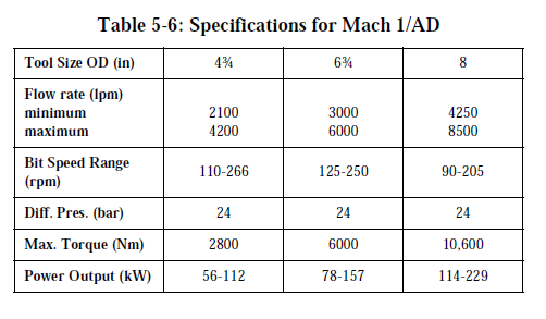
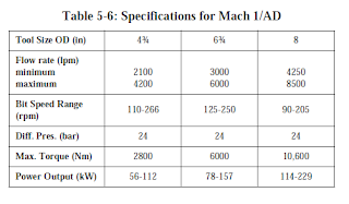
Downhole Motors - Positive Displacement Motors :Navi-Drill Mach 1/AD
Navi-Drill Mach 1/AD
The Navi-Drill Mach 1/AD motor is designed specifically for use in holes
drilled with air and mist. With an AKO, the steerable motor drilling system
combines directional and straight hole drilling capabilities to provide
precise directional control. Generally, in one run it can establish the desired
direction and inclination for the surface interval of a directional well.
The AKO places the bend close to the bit, and can be adjusted so the motor
housing tilt angle can be configured on the rig floor to settings from 0° -
2.5°. The resulting dogleg capability can be as high as 12°/100 ft. The
unique AKO design requires no shims to adjust the bent housing angle, so a
single motor can achieve a variety of build rates.
This motor, with the AKO, can perform directional work when oriented in
a particular direction, and is capable of drilling straight ahead when the
drillstring is rotating. This is accomplished by tilting the bit relative to the
motor and/or applying a side force at the bit while maintaining a minimum
amount of bit offset relative to the axis of the motor.
When an alignment bent sub (ABS) is fitted to the top of the motor and
used in conjunction with the AKO, the motor configuration can be used for
building angle, as in a fixed angle build motor. Orientation of the motor
and drillstring is possible in this configuration, but not rotation. The
maximum build rate possible from this configuration is approximately 20°/
100 ft.
Saturday, 13 February 2016
Downhole Motors - Positive Displacement Motors : Navi-Drill Mach 1 P/HF
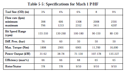
Navi-Drill Mach 1 P/HF
The Navi-Drill Mach 1 P/HF (High Torque/High Flow) is a positive
displacement motor that develops high torque at the bit at relatively low to
medium speed range (80-310 RPM). This makes it ideal for directional
applications, drilling with high weight-on-bit, or in areas where formations
require high torque due to specialized PDC bits.
The Navi-Drill Mach 1 P/HF motor has a multi-lobe rotor/stator
configuration which generates more torque than other motors.
A unique bearing assembly and improved elastomer compounds have
increased the Mach 1 P/HF’s hydraulic horsepower and extended its
operating life. The rotor/stator design allows a larger than normal flow rate
to be pumped through the motor, generating the higher torques. There is a
rotor nozzling system that allows the motor to run over the higher
maximum flow rate without exceeding maximum recommended motor
speed. These higher flow rates offer improved hole cleaning and bit
hydraulics.
The Navi-Drill Mach 1 P/HF offers the AKO (adjustable kick off sub)
which is rig floor adjustable between 0° - 2.75°, giving a BUR up to
12°/100 ft. Included in the design is a unique U-joint assembly which
allows the higher torque to be transmitted from the motor section through
the bearing assembly and to the bit.
Although primarily a directional performance drilling motor, the Navi-
Drill Mach 1 P/HF can also be used for straight-hole drilling.
Downhole Motors - Positive Displacement Motors : Navi-Drill Mach 2
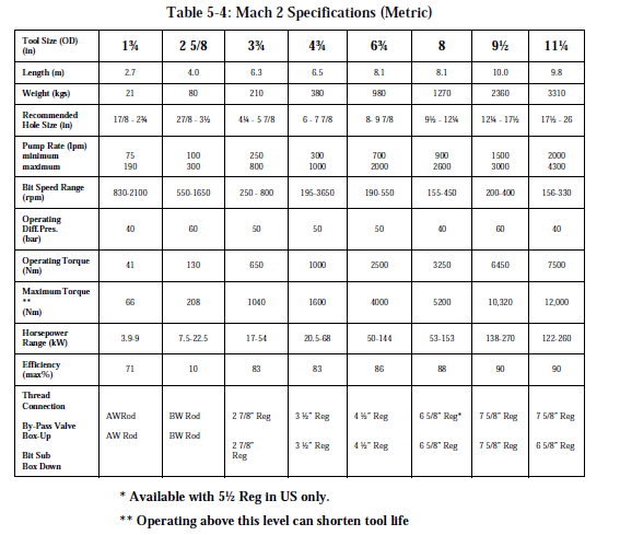
Navi-Drill Mach 2
The Navi-Drill Mach 2 is a positive-displacement motor that can improve
drill rates in both straight-hole and directional applications.
The Mach 2 has a multi-stage, 1/2 rotor/stator configuration, which
generates low to medium torque at medium speeds for higher penetration
rates with less weight-on-bit. This makes it a good choice for drilling
straight and directional holes in difficult formations. The motor is
particularly suited for long-interval performance drilling with natural
diamond, TSP, or PDC bits.
Mach 2 motors also come in 1-3/4”, 2-5/8” and 4-3/4” ODs for slimhole
applications.
Tables 5-3 and 5-4 list the Mach 2 specifications.

Downhole Motors - Positive Displacement Motors : Navi-Drill Mach 1C
Navi-Drill Mach 1C
The Mach 1C is a positive-displacement motor that develops high torque at
the bit at relatively low speed ranges (80-340 rpm). This makes it ideal for
directional applications, drilling with high weight-on-bit, navigation
drilling with roller cone or large cutter PDC bits, and coring operations.
The motor has a multi-lobe (5/6) rotor/stator configuration, which
generates higher torque than the 1/2 lobe motors, permitting more weighton-
bit and increasing the drill rate. Because the motor develops its power at
low speeds, it can improve bit performance without accelerating wear on
the bearings or cones.
A unique bearing assembly and improved elastomer compounds in the
stator have increased the Mach 1C’s hydraulic horsepower and extended
operating life. It also has a new rotor nozzling system that allows the motor
to be run at 50-100% over its maximum recommended flow rate without
exceeding maximum recommended motor speed. The additional mud
passes through the motor’s rotor, and flow rate can be adjusted by
interchanging nozzles. Higher rates offer improved hole cleaning and bit
hydraulics.
Although primarily a directional performance drilling motor, the Mach 1C
can also be used for straight-hole drilling.
Tables 5-1 and 5-2 detail the Mach 1C specifications.


Downhole Motors - Positive Displacement Motors : Characteristics
Characteristics
• Torque is directly proportional to the motor’s differential pressure.
This makes the tool a very simple to operate.
• RPM is directly proportional to flow rate, through somewhat affected
by torque output.
• Hydraulic horsepower consumed = {(P x Q) ¸ 1714}, where P is the
pressure drop (psi) across the motor and Q is flow rate (gpm).
Downhole Motors - Positive Displacement Motors : PDM Observations
PDM Observations
• Motor stall will be obvious due to an increase in surface pressure.
Motor stalling should be avoided as it erodes the service life of the
motor.
• LCM can be pumped safely, though care should be taken that the
material is added slowly and evenly dispersed. The system should not
be slugged.
• Sand content in the drilling fluid should be kept to a minimum.
• Temperature limits are around 270°F to 130ºC, but higher temperature
stators have been developed.
• Pressure drop through the tool while working is typically around 50
psi to 800 psi.
• Allowable wear on bearings is of the order of 1mm - 8mm, depending
upon tool size.
• The tool should be flushed out with water prior to laying down.
In general, drilling fluids with a low aniline point can damage the rubber
stator. As a rule, the nailine point in oil based muds should be around
150°F (60°C). Usually, this is related to the aromatic content which should
be equal to or less than 10%. Contact the local supplier if there is any
doubt.
If a by-pass nozzle is fitted to a multi-lobe rotor, then it must be sized very
carefully to allow the motor section to develop the necessary power. Any
variation in flow for which the nozzle was inserted will compromise the
motor’s performance.
Downhole Motors - Positive Displacement Motors : Types of Positive Displacement Motors
Types of Positive Displacement Motors
PDMs come in various configurations. As has been mentioned previously,
the stator will have one more lobe than the rotor. The first types of PDMs,
and the simplest, are 1/2 motors. These generally give medium to low
torque output and medium to high rotary speed. Torque output is directly
proportional to pressure drop across the motor. The
1/2 motors have good applications in performance drilling with a PDC,
diamond, or TSP-type bits. Some shorter models are used for directional
purposes.
Multi-lobe motors have high torque output and relatively slow speed.
Therefore, they have good applications with roller cone bits and for coring.
Such motors are also suitable for use with PDC bits, especially the large
cutter types which require a good torque output to be efficient. These tools,
being fairly short, also have good directional applications with bent subs as
the deflection device. Multi-lobe motors may be constructed with a hollow
rotor and a nozzle or blank placed in a holding device at the top. The nozzle
allows for high flow rates to be accommodated by by-passing the excess
flow from the motor section and the fluid will exit through the bit.
Downhole Motors - Positive Displacement Motors : Bearing Section
Bearing Section
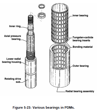
A typical positive displacement motor utilizes three sets of bearings
attached to a drive shaft. There are two sets of radial bearings (“upper” and
“lower”) with one set of axial thrust bearings.
The axial thrust bearing section supports the on and off bottom loading and
hydraulic thrust. It consists of a series of ball bearings stacked one on top
of the other, each set being contained in its own race (groove). The number
of these bearings will vary, depending on the size of the tool.
The upper and lower radial bearings are lined with tungsten carbide inserts.
These bearings support the concentrically rotating drive shaft against
lateral loads. The inherent design of the upper radial bearing limits the
amount of fluid flow diverted to cool and lubricate the bearing package.
This diversion of flow is typically 2 - 10%, depending on motor and bit
pressure drop. The major portion of the drilling fluid is collected by ports
in the drive shaft and exits through the bit. In some motors, diamond
bearings are used, which need up to 20% of the flow to be diverted,
depending upon conditions. Figure 5-23 illustrates typical bearing sections
found in PDMs.

Friday, 12 February 2016
Downhole Motors - Positive Displacement Motors : Connecting rod assemblies
Connecting rod assemblies
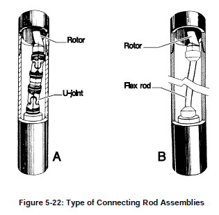
Since the rotor is spiral shaped, it does not rotate concentrically, rather it
traces a back and forth motion. This motion must be converted to a
concentric motion to be transmitted to the bit via the drive sub. This is
achieved by a connecting rod assembly. There are several types.
Universal-joint
U-joint assemblies (Figure 5-22a) have been utilized by the industry and
are still used in most positive displacement motors. The assembly consists
of two universal joints, each grease filled, and sealed with oil-resistant
reinforced rubber sleeves to protect them from drill fluid contamination. A
drawback of the U-joint assembly is the lack of sufficient strength for
higher torque applications, such as those encountered with recent
generations of high torque PDM’s, particularly when used with PDC bits.
This inherent weakness is a result of the manufacturing process whereby
the U-joint is “flame-cut” rather than machined.
Flex rod
A recent development in connecting rod assembly technology has been the
utilization of flexible steel or titanium “flex rods” (Figure 5-22b). While
flex rods are limited by the degree of allowable lateral bending, they have
the advantage of low maintenance, since they do not require lubricants or
rubber sleeves. Flex rods are now standard on most smaller Navi-Drills.
One recent approach has been to mount the flex rod inside the hollow rotor
of a short, high torque steerable PDM, rather than connecting it to the
bottom of the rotor. By connecting a long flex rod to the inside of the top
end of the rotor and extending it through the rotor, to connect to the top of
the drive sub assembly, the overall rate of bend is decreased due to its
increased length.

Downhole Motors - Positive Displacement Motors : Motor Section
Motor Section
This is a reverse application of Rene Moineau’s pump principle. The motor
section consists of a rubber stator and steel rotor. The simple type is a
helical rotor which is continuous and round. This is the single lobe type.
The stator is molded inside the outer steel housing and is an elastometer
compound. The stator will always have one more lobe than the rotor.
Hence motors will be described as 1/2, 3/4, 5/6 or 9/10 motors.
Both rotor and stator have certain pitch lengths and the ratio of the pitch
length is equal to the ratio of the number of lobes on the rotor to the
number of lobes on the stator.
As mud is pumped through the motor, it fills the cavities between the
dissimilar shapes of the rotor and stator. The rotor is forced to give way by
turning or, in other words, is displaced (hence the name). It is the rotation
of the rotor shaft which is eventually transmitted to the bit.

Downhole Motors - Positive Displacement Motors : By-Pass Valve
By-Pass Valve
The by-pass valve allows fluid to fill the drill string while tripping in the
hole and to drain while tripping out. When mud is pumped, the valve closes
causing fluid to move through the tool. Most valves are of a spring piston
type which closes under pressure to seal off ports to the annulus. When
there is no downward pressure, the spring forces the piston up so fluid can
channel through the ports to the annulus. (Figure 5-20).

Downhole Motors - Positive Displacement Motors
Positive Displacement Motors
A positive displacement motor (PDM) is a hydraulically driven downhole
motor that uses the Moineau principle to rotate the bit, independent of drill
string rotation. The PDM is made up of several sections:
• By-pass valve or dump sub.
• Motor section.
• Universal joint or connecting rod section.
• Bearing section with drive sub.

Downhole Motors
Downhole Motors
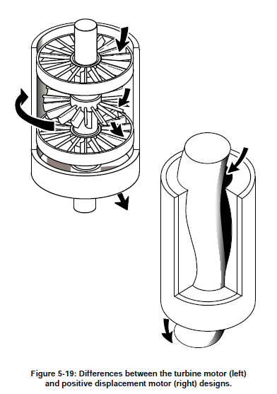
The idea of using downhole motors to directly turn the bit is not a new one.
One of the first commercial motors was turbine driven. The first patent for
a turbodrill existed in 1873. The USSR focused efforts in developing
downhole motors as far back as the 1920’s and has continued to use motors
extensively in their drilling activity. After 1945, the West focused efforts
more on rotary drilling, but field applications for downhole motors has
increased spectacularly from the 1980’s onwards.
A turbine consists of a multistage vane-type rotor and stator section, a
bearing section, a drive shaft and a bit rotating sub. A “stage” consists of a
rotor and stator of identical profile. The stators are stationary, locked to the
turbine body, and deflect the flow of drilling mud onto the rotors which are
locked to the drive shaft. As the rotors are forced to turn, the drive shaft is
also forced to turn, causing the bit sub and the bit to rotate
Thursday, 11 February 2016
Proximity (anti-collision) analysis
Proximity (anti-collision) analysis
On multi-well projects (particularly offshore) there are small distances
between slots. To eliminate the risk of collisions directly beneath the
platform, the proposed well path is compared to existing and other
proposed wells. The distances between the other wells and the proposal are
calculated at frequent intervals in critical sections. These calculations can
be performed using the EC*TRAK software (BHI) or COMPASS.
Survey uncertainty must also be computed for both the proposed well and
the existing wells. All major operating companies have established criteria
for the minimum acceptable separation of wells, which are usually linked
to “cone of error” or “ellipse of uncertainty” calculations.
Nudging - Planning a nudge program
Planning a nudge program
The directions in which the wells are “nudged'' should be chosen to achieve
maximum separation. Wells may not necessarily be nudged in their target
directions.
Nudges will not only be shown on the individual well plans for each well,
but a structure plot will also be drawn which will show well positions at the
surface casing point after the nudge.
Nudging - Techniques for “nudging”
Techniques for “nudging”
When formations are suitable (soft), jetting is the best technique to use.
The most common method is to use a mud motor of 9.5" OD or greater
with a 17.5" bit and a 1.5° bent sub. Using a 1.5° bent sub gives low build
rates and hence a low dogleg severity. The hole is then opened to the
required size after the mud motor run. Occasionally the job is performed
with a large mud motor and a 26" bit from the start. In this case either a
1.5°or 2° bent sub might be used.
Nudging
Nudging
The technique of “nudging” is used on platforms in order to “spread out”
conductors and surface casings, which minimizes the chance of a collision.
Basically, when the hole for surface casing is drilled, some angle is built at
a low rate (e.g. 1°/100') in the chosen direction.
In addition to “spreading things out”, other reasons for “nudging” are:
• to drill from a slot located on the opposite side of the platform from
the target, when there are other wells in between
• to keep wells drilled in the same general direction as far apart as
possible
• if the required horizontal displacement of a well is large compared to
the total vertical depth, then it is necessary to build angle right below
the surface conductor to avoid having to use a high build rate
Planning The Well Trajectory - Lead angle
Lead angle
In the old days (pre 1985) it was normal practice to allow a “lead angle”
when kicking off. Since roller cone bits used with rotary assemblies tend to
“walk to the right”, the wells were generally kicked off in a direction
several degrees to the left of the target direction. In extreme cases the lead
angles could be as large as 20°.
The greatly increased use of steerable motors and PDC bits for rotary
drilling have drastically reduced the need for wells to be given a “lead
angle”. Many wells today are deliberately kicked off with no lead angle
(i.e. in the target direction).
Planning The Well Trajectory - The horizontal projection
The horizontal projection
On many well plans, horizontal projection is just a straight line drawn from
the slot to the target. On multi-well platforms however, it is sometimes
necessary to start the well in a different direction to avoid other wells. Once
clear of these, the well is turned to aim at the target. This is a 3-dimensional
turn, but on the horizontal plan it would typically look like Figure 5-18.
The path of the drilled well is plotted on the horizontal projection by
plotting total North/South coordinates (Northings) versus total East/West
coordinates (Eastings). These coordinates are calculated from surveys.

Planning The Well Trajectory - Drop-off section
Drop-off section
On S-type wells, the rate of drop off is selected to ease casing problems and
avoidance of completion and production problems. It is much less critical
to drilling because there is less tension in the drill pipe that is run through
deeper doglegs and less time spent rotating below the dogleg.
On S-type wells, the rate of drop off is selected to ease casing problems and
avoidance of completion and production problems. It is much less critical
to drilling because there is less tension in the drill pipe that is run through
deeper doglegs and less time spent rotating below the dogleg.
Planning The Well Trajectory - Tangent Section
Tangent Section
During the eighties, a number of extended reach projects were successfully
completed. If wells are drilled at inclinations (up to 80°), the area which
can be covered from a single platform is approximately 8 times that
covered when maximum inclination of the wells is limited to 60°.
However, high inclination angles can result in excessive torque and drag on
the drill string and present hole cleaning, logging, casing, cementing and
production problems. These can generally be avoided with current
technology.
Experience over the years has shown that directional control problems are
aggravated when tangent inclinations are less than 15°. This is because
there is more tendency for the bit to walk (i.e. change in azimuth) so more
time is spent keeping the well on course. As such, most run-of-the-mill
directional wells are still planned with inclinations in the range 15° - 60°.
Wednesday, 10 February 2016
Planning The Well Trajectory - Kick-off Point and Build-Up Rate
Kick-off Point and Build-Up Rate
The selection of both the kick-off point and the build-up rate depends on
many factors. Several being hole pattern, casing program, mud program,
required horizontal displacement and maximum tolerable inclination.
Choice of kick-off points can be limited by requirements to keep the well
path at a safe distance from existing wells. The shallower the KOP and the
higher the build-up rate used, the lower the maximum inclination.
Build-up rates are usually in the range 1.5°/100' M.D. to 4.0°/100' M.D. for
normal directional wells. Maximum permissible dogleg severity must be
considered when choosing the appropriate rate.
In practice, well trajectory can be calculated for several KOPs and build-up
rates and the results compared. The optimum choice is one which gives a
safe clearance from all existing wells, keeps the maximum inclination
within desired limits and avoids unnecessarily high dogleg severities.
Tuesday, 9 February 2016
Planning The Well Trajectory - Horizontal wells and Allocation of slots to targets
Horizontal wells
For many applications, the best well profile is one in which the inclination
is built to 90° or even higher.
Allocation of slots to targets
Even this is not always a simple task. From a directional driller's
viewpoint, slots on the North East side of the platform or pad should be
used for wells whose targets are in a North Easterly direction.
Unfortunately there are other considerations (e.g. water injection wells
may have to be grouped together for manifolding requirements). Also, as
more wells are drilled and the reservoir model is upgraded, targets can be
changed or modified.
Inner slots are used to drill to the innermost targets (i.e. targets with the
smallest horizontal distances from the platform) and these wells will be
given slightly deeper kick-off points. The outer slots are used to drill to
targets which are furthest from the platform. These wells will be given
shallow kick-off points and higher build-up rates to keep the maximum
inclination as low as possible.
Planning The Well Trajectory - Catenary Curve Well Plan
Catenary Curve Well Plan
One suggestion for an efficient well path for directional wells would be to
plan the well as a continuous smooth curve, all the way from KOP to
target. This is the catenary method. A catenary curve is the natural curve
that a cable, chain or any other line of uniform weight assumes when
suspended between two points. A similar suspension of drill string would
also form a catenary curve.
Proponents of the catenary method argue that it results in a smoother
drilled wellbore, that drag and torque are reduced and that there is less
chance of key seating and differential sticking. However, in practice it is
hard to pick BHAs which will continuously give the required gradual rate
of build. It is in reality no easier to follow a catenary curve well plan than a
traditional well plan. Also, the catenary curve method produces a higher
maximum inclination than would result from the build and hold or S type
patterns.
Although the catenary method has been tried, with some success, it is not
widely used and it IS NOT Baker Hughes INTEQ policy to recommend
this type of well profile.
Planning The Well Trajectory - Types of Directional Patterns
Types of Directional Patterns
The advent of steerable systems has resulted in wells that are planned and
drilled with complex paths involving 3-dimensional turns. This is
particularly true in the case of re-drills, where old wells are sidetracked and
drilled to new targets.
These complex well paths are harder to drill and the old adage that “the
simplest method is usually the best” holds true. Therefore, most directional
wells are still planned using traditional patterns which have been in use for
many years. Common patterns for vertical projections are shown on the following pages:

Features:·
Shallow kick-off point (KOP)
Build-up section (which may have more than one build up rate)
Tangent section
Applications:
Deep wells with large horizontal displacements
Moderately deep wells with moderate horizontal displacement, where intermediate casing
is not required

Features: There are several variations:
Shallow KOP - Build, hold & drop back to vertical
Build-up section - Build, hold, drop & hold (illustrated above)
Tangent section - Build, hold & continuous drop through reservoir
Drop-off section
Applications: Disadvantages:
Multiple pay zones - Increased torque & drag
Reduces final angle in reservoir - Risk of keyseating
Lease or target limitations - Logging problems due to inclination
Well spacing requirements
Deep wells with small horizontal displacements

Features:
Deep KOP
Build-up section
Short tangent section (optional)
Applications:
Appraisal wells to assess the extent of a newly discovered reservoir
Repositioning of the bottom part of the hole or re-drilling
Salt dome drilling
Disadvantages:
Formations are harder so the initial deflection may be more difficult to achieve
Harder to achieve desired tool face orientation with downhole motor deflection assemblies
(more reactive torque)
Longer trip time for any BHA changes required
On multi-well platforms, only a few wells are given deep kick-off points,
because of the small slot separation and the difficulty of keeping wells
vertical in firmer formation. Most wells are given shallow kick-off points
to reduce congestion below the platform and to minimize the risk of
collisions.
Planning The Well Trajectory - The Target
The Target
The target is usually specified by the geologist, who will not merely define
a certain point as the target but also specify the acceptable tolerance (e.g. a
circle of radius 100 feet having the exact target as its center). Target zones
should be selected as large as possible to achieve the objective. If multiple
zones are to be penetrated, they should be selected so that the planned
pattern is reasonable and can be achieved without causing drilling
problems.
Planning The Well Trajectory
Planning The Well Trajectory
One area of well planning in which directional companies are closely
involved is the planning of the well trajectory. Again, this is not as simple a
task as it might seem at first glance, particularly on a congested multi-well
platform. There area number of aspects that must be carefully considered
before calculating the final well path.
Well Planning - Field Coordinates
Field Coordinates
Although the coordinates of points on a wellpath could be expressed as
UTM coordinates, it is not normal practice. Instead, a reference point on
the platform or rig is chosen as the local origin and given the coordinates
0,0. On offshore platforms this point is usually the center of the platform.
The Northings and Eastings points on the wells drilled from the platform
are referenced to this single origin. This is important when comparing
positions of wells, in particular for anti-collision analysis.
Direction Measurements
Survey tools measure the direction of the wellbore on the horizontal plane
with respect to North reference, whether it is True or Grid North. There are
two systems:
Azimuth.
In the azimuth system, directions are expressed as a clockwise angle from
0° to 359.99°, with North being 0°.
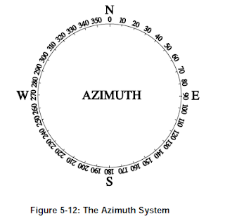
Quadrant Bearings
In the quadrant system , the directions are expressed as angles
from 0°-90° measured from North in the two Northern quadrants and from
South in the Southern quadrants. The diagram in Figure 5-14 illustrates
how to convert from the quadrant system to azimuth, and vice versa.

Friday, 5 February 2016
Well Planning - Reference Systems and Coordinates, (3) Azimuth Reference Systems
Azimuth Reference Systems
For directional surveying there are three azimuth reference systems:
• Magnetic North
• True (Geographic) North
• Grid North
All “magnetic-type” tools give an azimuth (hole direction) referenced to
Magnetic North. However, the final calculated coordinates are always
referenced to either True North or Grid North.
True (Geographic) North
This is the direction of the geographic North Pole which lies on the Earth’s
axis of rotation. Direction is shown on maps using meridians of longitude.
Grid North
Drilling operations occur on a curved surface (i.e, the surface of the Earth)
but when calculating horizontal plane coordinates a flat surface is assumed.
Since it is not possible to exactly represent part of the surface of a sphere
on a flat well plan, corrections must be applied to the measurements. To do
this, different projection systems which can be used.
UTM System
One example of a grid system is the Universal Transverse Mercator (UTM)
System. In transverse mercator projection, the surface of the spheroid
chosen to represent the Earth is wrapped in a cylinder which touches the
spheroid along a chosen meridian. (A meridian is a circle running around
the Earth passing through both North and South geographic poles.)
These meridians of longitude converge towards the North Pole and do not
produce a rectangular grid system. The grid lines on a map form the
rectangular grid system, the Northerly direction of which is determined by
one specified meridian of longitude. This “Grid North” direction will only
be identical to “True North” on a specified meridian.
Well Planning - Reference Systems and Coordinates, (2) Inclination References
Inclination References
The inclination of a well-bore is the angle (in degrees) between the vertical
and the well bore axis at a particular point. The vertical reference is the
direction of the local gravity vector and could be indicated by a plumb bob.
The inclination of a well-bore is the angle (in degrees) between the vertical
and the well bore axis at a particular point. The vertical reference is the
direction of the local gravity vector and could be indicated by a plumb bob.
Well Planning - Reference Systems and Coordinates.- (1) Depth References
Depth References
During the course of a directional well, there are two kinds of depths:
• Measured Depth (MD) is the distance measured along the actual
course of the borehole from the surface reference point to the survey
point. This depth is always measured in some way, for example, pipe
tally, wireline depth counter, or mud loggers depth counter.
• True Vertical Depth (TVD) is the vertical distance from the depth
reference level to a point on the borehole course. This depth is always
calculated from the deviation survey data.
In most drilling operations the rotary table elevation is used as the working
depth reference. The abbreviation BRT (below rotary table) and RKB
(rotary kelly bushing) are used to indicate depths measured from the rotary
table. This can also be referred to as derrick floor elevation. For floating
drilling rigs the rotary table elevation is not fixed and hence a mean rotary
table elevation has to be used.
In order to compare individual wells within the same field, a common
depth reference must be defined and referred to (e.g. When drilling a relief
well into a blow-out well, the difference in elevation between the
wellheads has to be accurately known). Offshore, mean sea level (MSL) is
sometimes used. Variations in actual sea level from MSL can be read from
tide tables or can be measured.
Well Planning - Reference Systems and Coordinates.
Reference Systems and Coordinates
With the exception of Inertial Navigation Systems, all survey systems
measure inclination and azimuth at a particular measured depth (depths
measured “along hole”). These measurements are tied to fixed reference
systems so that the course of the borehole can be calculated and recorded.
These reference systems include:
• Depth references
• Inclination references
• Azimuth references
Well Planning - Introduction
Well Planning
Introduction
There are many aspects involved in well planning, and many individuals
from various companies and disciplines are involved in designing various
programs for the well (mud program, casing program, drill string design,
bit program, etc). A novel approach to well planning is one where the
service contractors become equally involved in their area of expertise.
This section will concentrate on those aspects of well planning which have
always been the province of directional drilling companies.
Thursday, 4 February 2016
Shoreline Drilling.
Shoreline Drilling.
In the case where a reservoir lies offshore but quite close to land, the most
economical way to exploit the reservoir may be to drill directional wells
from a land rig on the coast.

These are only some of the many applications of directional drilling.
Although it is not a new concept, one type of directional drilling, horizontal
drilling, is the fastest growing branch of drilling, with major advances
occurring in tools and techniques. As with directional drilling, there are
numerous specific applications for horizontal drilling.
Salt Dome Drilling
Salt Dome Drilling
Directional drilling programs are sometimes used to overcome the
problems of drilling near salt domes. Instead of drilling through the salt,
the well is drilled at one side of the dome and is then deviated around and
underneath the overhanging cap.

Directional drilling programs are sometimes used to overcome the
problems of drilling near salt domes. Instead of drilling through the salt,
the well is drilled at one side of the dome and is then deviated around and
underneath the overhanging cap.

Wednesday, 3 February 2016
Fault Drilling
Fault Drilling
Directional wells are also drilled to avoid drilling a vertical well through a
steeply inclined fault plane which could slip and shear the casing.

Directional wells are also drilled to avoid drilling a vertical well through a
steeply inclined fault plane which could slip and shear the casing.

Inaccessible locations
Inaccessible locations
Directional wells are often drilled because the surface location directly
above the reservoir is inaccessible, either because of natural or man-made
obstacles.

Directional wells are often drilled because the surface location directly
above the reservoir is inaccessible, either because of natural or man-made
obstacles.

Sidetracking
Sidetracking
Sidetracking out of an existing wellbore is another application of
directional drilling. This is done to bypass an obstruction (“fish”) in the
original wellbore, to explore the extent of a producing zone in a certain
sector of a field, or to sidetrack a dry hole to a more promising target.
Wells are also sidetracked to access more reservoir by drilling a horizontal
hole section from the existing well bore.

Controlling Vertical Wells
Controlling Vertical Wells
Directional techniques are used to “straighten crooked holes”. When
deviation occurs in a well which is supposed to be vertical, various
techniques can be used to bring the well back to vertical. This was one of
the earliest applications of directional drilling.
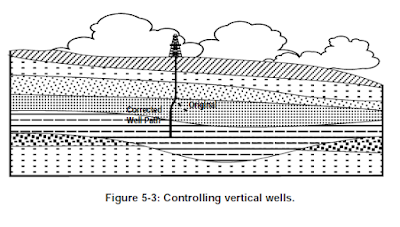
Directional techniques are used to “straighten crooked holes”. When
deviation occurs in a well which is supposed to be vertical, various
techniques can be used to bring the well back to vertical. This was one of
the earliest applications of directional drilling.

Relief Wells
Relief Wells
Directional techniques are used to drill relief wells in order to “kill”
blowouts. Relief wells are deviated to pass as close as possible to the
uncontrolled well. Heavy mud is pumped into the reservoir to overcome
the pressure and bring the wild well under control.

Directional techniques are used to drill relief wells in order to “kill”
blowouts. Relief wells are deviated to pass as close as possible to the
uncontrolled well. Heavy mud is pumped into the reservoir to overcome
the pressure and bring the wild well under control.
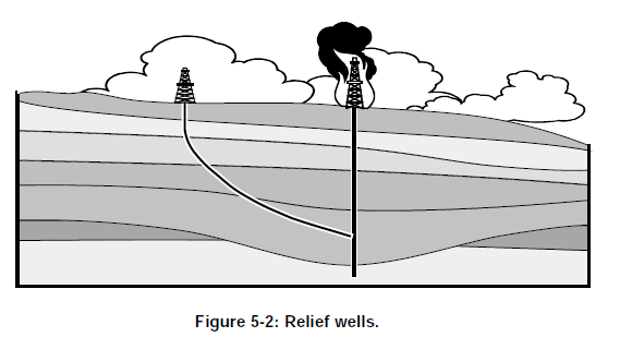
Multiple wells from offshore structures
Multiple wells from offshore structures
The most common application of directional drilling techniques is in
offshore drilling. Many oil and gas deposits are situated well beyond the
reach of land based rigs. Drilling a large number of vertical wells from
individual platforms is both impractical and uneconomical. The obvious
approach for a large oilfield is to install a fixed platform on the seabed,
from which many directional boreholes can be drilled. The bottomhole
locations of these wells are carefully spaced for optimum recovery.

In conventional development, wells cannot be drilled until the platform has
been constructed and installed. This can mean a delay of several years
before production begins. Such delay scan be considerably reduced by predrilling
some of the wells through a subsea template while the platform is
being constructed. These wells are directionally drilled from a semisubmersible
rig and tied back to the platform once it has been installed.
Definition of Directional Drilling
Definition of Directional Drilling
Directional drilling can generally be defined as the science of directing a
wellbore along a predetermined trajectory to intersect a designated subsurface
target.
Directional drilling can generally be defined as the science of directing a
wellbore along a predetermined trajectory to intersect a designated subsurface
target.
Directional Drilling
Directional Drilling
Upon completion of this chapter, you should be able to:
• Describe the general aspects involved in well planning.
• Describe the main features of the common well patterns and list
the applications and disadvantages of each.
• State the two basic types of downhole motor and give a simple
explanation of the operating principles of each.
• Explain what is meant by “reactive torque” and the importance
of this in directional drilling.
• List the main deflection tools available and state the advantages
and disadvantages of each.
• Explain what is meant by the “toolface” of a deflection tool.
• Define and explain the terms “Tool Face Orientation”, “High
Side Tool Face”, and “Magnetic Tool Face”.
• List the main factors which affect the directional behavior of
rotary assemblies.
• Explain the Fulcrum, Stabilization and Pendulum principles.
• Explain what is meant by the terms “steerable motor” and
“Navigation Drilling System”.
• Explain the concept of “three-point geometry” and calculate the
“Theoretical Geometric Dogleg Severity” (TGDS) of a
Navigation System.
• Explain the differences between “Conventional” and
“Navigational” drilling systems
Use Of Torque & Drag Programs For BHA Weight Evaluation
Use Of Torque & Drag Programs For BHA Weight Evaluation
These programs have a wide range of applications, but have mainly been
used to evaluate drillstring design integrity and alternative well plans for
horizontal wells or complex, unusual directional wells. However, the
program can be used to check BHA weight calculations for normal
directional wells. The program will calculate axial drag for a non-rotated
assembly and also calculates the position of the neutral point in the
drillstring. In addition, the program calculates the forces on the drill pipe
and will “flag” any values of compressive load which exceed the critical
buckling force for the drill pipe.

The E*C TRAK Torque and Drag Module
The E*C TRAK Torque and Drag Module
This program, developed at the Drilling Research Center in Celle,
Germany, is used to calculate torque and drag when a friction factor
(coefficient of sliding friction) is known or estimated. It will calculate the
friction factor when either torque or hookload is known.
Software accuracy has been verified against actual field data, with inputs
and outputs handled in user selected units.
General Uses
The program may be used to:
• Optimize well path design for minimum torque and drag
• Analyze problems either current or post-well
• Determine drillstring design limitations
• Determine rig size requirements
Inputs Required
• Drillstring component data (OD, ID, tool joint, and material
composition)
• Survey data (actual or planned)
• Friction factor(s) or actual hookload or torque values (for friction
factor calculation)
Outputs
Information concerning loads, torques and stresses are calculated for
discrete points in the drillstring from rotary table to the bit. These values
are output in both tabular (summary or detailed) and graphical formats:
• Drag load (pick-up or slack-off)
• Pick up load
• Slackoff load
• Rotating off bottom load
• Drilling load
• Rotating off bottom torque
• Rotary torque (drilling and off-bottom)
• Maximum allowable hook load (at minimum yield)
• Drillstring weight (in air)
• Bit to neutral point distance drillstring twist
• Drillstring twist
• Axial stress
• Torsional stress
• Bending stress
• Total equivalent stress
Tuesday, 2 February 2016
Computer Models of Drillstring Friction
Computer Models of Drillstring Friction
Proper evaluation of drillstring friction requires the use of a computer
program. These programs analyze drillstring friction for rotary drilling as
well as drilling with no drillstring rotation.
These mathematical models make a number of simplifying assumptions
and consider the drillstring as composed of discrete elements. Using these
models, it is possible to solve equations for the normal force of drillstring/
well bore contact at the bottom drillstring element, the friction force
deriving from that normal contact force, and the load condition at the upper
end of the drillstring element. Such methods, repeated for each drillstring
element over the length of the drillstring, yield the following information:
• Surface hookload and rotary torque
• Normal forces of drillstring/well bore contact at each drillstring
element
• Average torsional and tensile load acting upon each drillstring
element
Along Hole Components of Force
Along Hole Components of Force
Consider a short element of a BHA which has a weight W.
Effective weight in drilling mud = W(BF)
Component of weight acting along borehole = W(BF)cosq
If the BHA is not rotated, the force of friction, FFR acting up the borehole
on the BHA element is given by:
FFR = mN
...where m is the coefficient of friction,
N is the normal reaction force between the BHA element and the borehole
wall. If this normal reaction is due only to the weight of the BHA element
itself, then:
N = W(BF)sinq and hence
FFR = mW(BF)sinq
The net contribution to the WOB from this BHA element is therefore
WBIT = W (BF) (cosq - msinq)
Along Hole Components of Force
Along Hole Components of Force
Consider a short element of a BHA which has a weight W.
Effective weight in drilling mud = W(BF)
Component of weight acting along borehole = W(BF)cosq
If the BHA is not rotated, the force of friction, FFR acting up the borehole
on the BHA element is given by:
FFR = mN
...where m is the coefficient of friction,
N is the normal reaction force between the BHA element and the borehole
wall. If this normal reaction is due only to the weight of the BHA element
itself, then:

Torque & Drag
Torque & Drag
Several factors affect hole drag, including hole inclination, dogleg severity,
hole condition, mud properties, hole size, and drillstring component types,
sizes and placement. However, as mentioned earlier, in drilling situations
where the drillstring is not rotated (as when a steerable system is used in
the oriented mode) axial drag can become very significant and should be
evaluated using a Torque and Drag computer program. Torque and Drag
programs can be found in EC*Track and DrillByte.
MSc in Oil and Gas Management
WHY CHOOSE THIS COURSE?
This course aims to equip you with the skills required to support a range of management/professional careers in the global petroleum industry. It provides a comprehensive advanced level introduction to the international operation of the industry (upstream and downstream), and explores the key challenges and emerging technologies that are influencing exploration and production and the future of oil and gas.
Core modules focus on essential skills for industry managers/professionals such as project and quality management, health and safety management and petroleum contracts and economics.
 This course is ideal for a person who is interested in a professional career in the energy and hydrocarbon industry. It is also suitable as a means of career enhancement for those already working in the industry. It is designed to benefit students from a range of technical, non-technical and commercial backgrounds. The course provides an understanding of the processes, drivers, threats and opportunities related to the management of the energy and hydrocarbon industry in the 21st century. It adopts a multidisciplinary approach, incorporating modules from various specialist areas including petroleum contracts and economics, project management, renewable energy, risk management, environmental management, strategic and human resource management.
Mandatory subjects for all routes
- Introduction to Oil & Gas Industry
- The Future of Oil and Gas
- HSE Management in the Oil & Gas Industry
- Petroleum Contracts & Economics
- Project & Quality Management in the Energy Industry
- Impacts of Petroleum Exploration, Extraction & Transportation
- Personal project under the guidance of an experienced supervisor
Optional subjects for the different routes
Technology Management Route
- Water & Wastewater Treatment
- Oil Spill Science, Response & Remediation
QHSE Route
- Risk Safety & Governance
- Oil Spill Science, Response & Remediation
Finance & Investment Route
- Investment Analysis and Decision Making in the Petroleum Industry
- International Oil & Gas Trading
Law & Policy Route (this route is not available for May start)
- International Environmental Law
- International Oil & Gas Trading
1) Oil and Gas Management MSc - Coventry University
2) MSc in Management - Oil and Gas - University of Liverpool
3)MSc in Project Management - Oil and Gas | London school of business and finance
4) university of central lancashire
5) GSM London
6) Birmingham city university
7) university of wolverhampton
Calculating BHA Weight With Drill Pipe In Compression - Summary
Calculating BHA Weight With Drill Pipe In Compression
Summary
• When drilling vertical wells, ordinary drill pipe must NEVER be run
in compression, in any hole size. Therefore, sufficient BHA weight
must be used to provide all the desired weight on bit with an
acceptable safety margin, except at higher inclinations.
• In large hole sizes (16-inch or greater) drill pipe should not be run in
compression.
• In smaller hole sizes on high-angle wells (over 45°), drill pipe may be
run in compression to contribute to the weight on bit, provided the
maximum compressive load is less than the critical buckling force.
This critical buckling force is the minimum compressive force which
will cause sinusoidal buckling of the drill pipe.
• A safety margin of at least 10% should be used in the calculation to
allow for some drag (friction) in the hole. However, axial drag is not a
major factor when assemblies are rotated.
The majority of the preceding discussion concerned rotary assemblies.
However, it would also apply to steerable motor systems used in the
rotary mode, with only minimal oriented drilling anticipated, the
required BHA weight could be calculated the same way. If a
significant amount of oriented drilling was likely, then the drag in the
hole should be evaluated using Torque and Drag computer programs.
In this type of situation, a proper engineering analysis of BHA weight
requirements is advised.
BHA Weight For Steerable Motor Assemblies
BHA Weight For Steerable Motor Assemblies
In practice, BHA weight for steerable assemblies on typical directional
wells is not a problem for the following reasons.
• The WOB is usually fairly low, especially when a PDC bit is used.
• When the drillstring is not rotated, the drill pipe is not subjected to the
cyclical stresses which occur during rotary drilling. Therefore,
sinusoidal buckling can be tolerated when there is no rotation of the
drillstring. Helical buckling however, must be avoided.
Helical buckling occurs at 1.41 FCR, where FCR is the compressive force
at which sinusoidal buckling occurs.
Therefore, if BHA weight requirements are evaluated as for rotary drilling,
the results should be valid for steerable systems in the oriented mode
except for unusual well paths which create exceptionally high values of
axial drag.
Monday, 1 February 2016
BHA Requirements When The Drillstring Is Not Rotated
BHA Requirements When The Drillstring Is Not Rotated
As stated earlier, when the drillstring is rotated, the component of sliding
friction (drag) is small and may be compensated for by using a safety factor
in BHA weight calculations. Drillstring friction for rotary assemblies will
mainly affect torque values. When the drillstring is not rotated (a steerable
motor system in the oriented mode) axial drag can become very significant
and drillstring friction should be evaluated.
A proper analysis of drillstring friction is more complex and must take into
account a number of factors, including wellbore curvature.
Calculating BHA Weight With Drill Pipe In Compression
Calculating BHA Weight With Drill Pipe In Compression
This means that on high-angle wells in small hole sizes, a fraction of the
weight on bit can safely be provided by having drill pipe in compression. It
is suggested that 90% of the critical buckling force be used as the
maximum contribution to the weight on bit from ordinary drill pipe.
Denoting the total air weight of the BHA by WBHA the weight on bit by
WBIT and the critical buckling load by FCR, we have:

Continuing example 4.5, recalculate the weight of the BHA required
(assuming some drill pipe is to be run in compression).
Suppose we are using New 5-inch Grade E drill pipe with 4.5-inch IF
connections.
Referring to the table for 5-inch drill pipe in a 12.25-inch hole, we see that
the critical buckling load at 60° inclination is approximately 26,000 lbs.
Our formula then gives:

Thus, a total air weight of 82,000 lbs is required. This is much more
feasible than the value of 138,000 lbs which was previously calculated.
Calculating Critical Buckling Force
Calculating Critical Buckling Force
Calculate the critical buckling load for 4.5-inch grade E drill pipe with a
nominal weight of 16.6 lb/ft (approximate weight 17.98 lb/ft; tool joint OD
6.375 inches: from API RP7G, Table 2.10) in an 8.5-inch hole at 50°
inclination.
1. Young's modulus, E, for steel is 29 x 10 psi

4.5-inch drill pipe with a nominal weight of 16.6 lbs/ft has an ID
of 3.826 inches. This information can be found under “New Drill
Pipe Dimensional Data” in the API RP-7G.

3. The approximate air weights for different sizes of drill pipe can
also be found in the API RP-7G.
Air weight = 17.98 lb/ft = 1.498 lb/in

Critical Buckling Force = 30,769 lbs
Running Drill Pipe In Compression
Running Drill Pipe In Compression
Example
Prior to drilling a 12.25-inch tangent section in a hard formation using an
insert bit, the directional driller estimates that they expect to use 50,000 lbs
WOB. The hole inclination is 60° and the mud density is 11 ppg.
What air weight of BHA is required if we are to avoid running any drill
pipe in compression? Use a 15% safety margin.

This is roughly the weight of ten stands of 8-inch drill collars, or
attentively, six stands of 8-inch collars plus 44 joints of HWDP!
This is just not practical! It would be a long, stiff and expensive BHA.
Critical Buckling Force
Dawson and Paslay developed the following formula for critical buckling
force in drill pipe.

where E is Young's modulus.
I is axial moment of inertia.
W is buoyed weight per unit length.
q is borehole inclination.
r is radial clearance between the pipe tool joint and the
borehole wall.
If the compressive load reaches the FCR, then sinusoidal buckling occurs.
This sinusoidal buckling formula can be used to develop graphs and tables
(see pages 4-18 through 4-23). If the compressive load at a given
inclination lies below the graph, then the drill pipe will not buckle. The
reason that pipe in an inclined hole is so resistant to buckling is that the
hole is supporting and constraining the pipe throughout its length. The low
side of the hole tends to form a trough that resists even a slight
displacement of the pipe from its initial straight configuration.
The graphs and tables provided in this section are for specific pipe/hole
configurations and may be used to look up the critical buckling force. The
following example illustrates how to calculate the critical buckling load.
Example
Prior to drilling a 12.25-inch tangent section in a hard formation using an
insert bit, the directional driller estimates that they expect to use 50,000 lbs
WOB. The hole inclination is 60° and the mud density is 11 ppg.
What air weight of BHA is required if we are to avoid running any drill
pipe in compression? Use a 15% safety margin.
This is roughly the weight of ten stands of 8-inch drill collars, or
attentively, six stands of 8-inch collars plus 44 joints of HWDP!
This is just not practical! It would be a long, stiff and expensive BHA.
Critical Buckling Force
Dawson and Paslay developed the following formula for critical buckling
force in drill pipe.
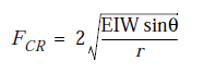
where E is Young's modulus.
I is axial moment of inertia.
W is buoyed weight per unit length.
q is borehole inclination.
r is radial clearance between the pipe tool joint and the
borehole wall.
If the compressive load reaches the FCR, then sinusoidal buckling occurs.
This sinusoidal buckling formula can be used to develop graphs and tables
(see pages 4-18 through 4-23). If the compressive load at a given
inclination lies below the graph, then the drill pipe will not buckle. The
reason that pipe in an inclined hole is so resistant to buckling is that the
hole is supporting and constraining the pipe throughout its length. The low
side of the hole tends to form a trough that resists even a slight
displacement of the pipe from its initial straight configuration.
The graphs and tables provided in this section are for specific pipe/hole
configurations and may be used to look up the critical buckling force. The
following example illustrates how to calculate the critical buckling load.
Required BHA Weight For Rotary Assemblies
Required BHA Weight For Rotary Assemblies
When two contacting surfaces (i.e drillpipe and the borehole wall) are in
relative motion, the direction of the frictional sliding force on each surface
will act along a line of relative motion and in the opposite direction to its
motion. Therefore, when a BHA is rotated, most of the frictional forces
will act circumferentially to oppose rotation (torque), with only a small
component acting along the borehole (drag).
Measurements of downhole WOB by MWD tools has confirmed that when
the BHA is rotated there is only a small reduction in WOB due to drag.
This reduction is usually compensated for by using a “safety factor”.
Consider a short element of the BHA which has a weight “W” (see
following figure). Neglecting drag in the hole:
Effective weight in mud = W (BF)
Component of weight acting along borehole = W (BF) cosq
... where Q is the borehole inclination
Extending this discussion to the whole BHA,
WBIT = WBHA (BF) cosq
... where WBHA is the total air weight of the BHA and WBIT is the weight
on bit.
Therefore, if no drill pipe is to be run in compression
BHA Weight & Weight-On-Bit
BHA Weight & Weight-On-Bit
One important consideration in designing the BHA is determining the
number of drill collars and heavy-weight pipe required to provide the
desired weight-on-bit. When drilling vertical wells, standard practice is to
avoid putting ordinary drill pipe into compression (recommended by
Lubinski in 1950). This is achieved by making sure that the “buoyed
weight” of the drill collars and heavy-weight pipe exceed the maximum
weight-on-bit. This practice has also been adopted on low inclination,
directionally drilled wells.
In other types of directional wells, it must be remembered that since gravity
acts vertically, only the weight of the “along-hole” component of the BHA
elements will contribute to the weight-on-bit. The problem this creates is
that if high WOB is required when drilling a high inclination borehole, a
long (and expensive) BHA would be needed to prevent putting the drillpipe
into compression. However, for these high inclination wells, it is common
practice to use about the same BHA weight as used on low inclination
wells.
On highly deviated wells, operators have been running drillpipe in
compression for years. Analysis of drillpipe buckling in inclined wells, by
a number of researchers (most notably Dawson and Paslay), has shown that
drillpipe can tolerate significant levels of compression in small diameter,
high inclination boreholes. This is because of the support provided by the
“low-side” of the borehole.
Drillpipe is always run in compression in horizontal wells, without
apparently causing damage to the drillpipe.
Higher Grade Pipe In The Inclined Section Of The Well
Higher Grade Pipe In The Inclined Section Of The Well
The previous discussion was restricted to the simple case when the higher
grade pipe is totally in the vertical portion of the well. If the higher grade
pipe is used through a build-up section, the calculation becomes more
difficult. A rough approximation could be obtained by treating each stand
length as a straight section of hole and using the average inclination of that
course length. The weight this exerts along the borehole is found from:
Weight acting along borehole = weight of stand x cos (ave. inc.)
This, however, ignores drag which may be significant.
Similarly, for an inclined section of the well where the inclination is
constant, the weight acting along hole will be the air-weight of the pipe
multiplied by the cosine of the average inclination. Notice again that in this
particular calculation we do not use a buoyancy factor. This is because
although the entire drillstring is subject to a buoyancy force, that force is
acting on the lower portion of the string and affects the weight pulling
down on the top joint of lower grade pipe from below, but not the weight of
the joints of higher grade pipe at the top of the string.
It must be emphasized that if a higher grade pipe extends below the vertical
part of the well, then an accurate analysis of the axial stresses requires the
use of “Torque and Drag” programs.
Maximum Hookload When Two Grades Of Drill Pipe Are Used
Maximum Hookload When Two Grades Of Drill Pipe Are Used
When two grades of drill pipe are used, the higher grade (i.e. the pipe with
the higher load capacity) is placed above the lower grade pipe. The
maximum tension to which the top joint can be subjected is based on the
yield strength of the higher grade of pipe. Calculations similar to those
already dealt with may be used to determine the maximum length of both
grades of pipe.
Another consideration is the maximum hookload which can be applied
when only a few stands of the higher grade pipe have been added. Provided
the higher grade pipe is in the vertical section, maximum hookload (pickup
load) is calculated as the yield strength of the lower grade of pipe PLUS
the “air weight” of the higher grade pipe. This is because the surface
hookload includes the weight of the higher grade pipe; but that weight
(since it is supported from the surface) does not act on the top joint of
lower grade pipe.
Maximum Hookload = Yield Strength + Weight
Of Lower Grade Pipe Of Higher Grade Pipe
When a sufficient length of higher grade pipe has been added, the limiting
condition will become the yield strength of the higher grade pipe.
The air weight of the higher grade pipe is used because the buoy force
acting on the drillstring is acting on the bit and components of the BHA.
The hydrostatic pressure which the mud exerts on the drill pipe in the upper
(vertical) section of the hole does not create a resultant force acting
upwards.
Buoyancy & Hookload - Overpull
Overpull
In tight holes or stuck pipe situations, the operator must know how much
additional tension, or pull, can be applied to the string before exceeding the
yield strength of the drill pipe. This is known as Overpull, since it is the
pull force over the weight of the string. For example, in a vertical hole with
12 ppg mud, a drillstring consists of 600 feet of 7.25-inch x 2.25-inch drill
collars and 6,000 ft of 5-inch, New Grade E drill pipe with a nominal
weight of 19.5 lbs/ft and an approximate weight of 20.89 lbs/ft.
First, the hookload is determined
Hookload = Air Weight x Buoyancy Factor
= [(6,000 x 20.89) + (600 x 127)] 0.817
= 164,658 pounds
Referring to the API RP 7G, the yield strength in pounds for this grade,
class, size and nominal weight of drill pipe is 395,595 pounds. Therefore:
Maximum Overpull = Yield Strength In Pounds - Hookload
= 395,595 - 164,658
= 230,937 pounds
The operator can pull 230,937 pounds over the hookload before reaching
the limit of elastic deformation (yield strength). Obviously, as depth
increases, hookload increases, at a certain depth the hookload will equal
the yield strength (in pounds) for the drill pipe in use. This depth can be
thought of as the maximum depth that can be reached without causing
permanent elongation of the drill pipe (disregarding hole drag as a
consideration). Practically, an operator would never intend to reach this
limit. A considerable safety factor is always included to allow for overpull
caused by expected hole drag, tight hole conditions or a stuck drillstring.
In practice, selection of the drill pipe grade is based upon predicted values
of pick-up load. For a directional well, the prediction of pick-up load is
best obtained using a Torque and Drag program, as well as including the
capacity for overpull. Some operators include an additional safety factor by
basing their calculations on 90% of the yield strength values quoted in API
RP7G.
Buoyancy & Hookload - Introduction
Buoyancy & Hookload
Introduction
Drillstrings weigh less in weighted fluids than in air due to a fluid property
known as buoyancy. Therefore, what is seen as the hookload is actually the
buoyed weight of the drillstring. Archimedes’s principle states that the
buoy force is equal to the weight of the fluid displaced. Another way of
saying this is that a buoy force is equal to the pressure at the bottom of the
string multiplied by the cross sectional area of the tubular. This is due to
the fact that the force of buoyancy is not a body force such as gravity, but a
surface force.
For example, the buoy force exerted on 7.5-inch x 2-inch drill collars in a
700 ft vertical hole with 12 ppg mud would be 17,925 pounds.
Buoy Force = Pressure x Area
Hydrostatic Pressure = 0.0519 x MW x TVD
= 0.0519 x (12) x (700)
= 436.8 psi
Cross Sectional Area = p/4 x (OD2 - ID2)
= p/4 x (7.52 - 22)
= p/4 x (56.25 - 4)
= 41.04 in2
Buoy Force = 436.8 x 41.04
= 17,924.99 pounds
By looking at the API RP 7G it can be determined that the air weight of
these 7.5-inch drill collars is 139 pounds per foot. If we have 700 feet of
collars, the total air weight would be 97,300 pounds.
Total Air Weight = weight per foot x length
= 139 x 700
= 97,300 pounds
The buoyed weight of the collars, or the Hookload, is equal to the air
weight minus the buoy force.
Hookload = Air Weight - Buoy Force
= 97,300- 17,925
= 79,375 pounds
This method for determining the buoyed weight is not normally used.
Instead, the following formula, which incorporates a buoyancy factor, is
used and recommended by the API.
MW=Mud Density (ppg)
Hookload = Air Weight x Buoyancy Factor
= 97,300 x 0.817
= 79,494 pounds
Buoyancy Factors rounded off to three places can also be found in the API
RP 7G (Table 2.13).
Note: The formula above for hookload does not take into
account axial drag. Hookload, as determined in the
formula above is the approximate static surface hookload
that would be displayed by the weight indicator in a
vertical hole with no drag, excluding the weight of the
traveling block, drill line etc.
In practice, hookload will vary due to motion and hole drag. Pick-Up Load
refers to the hookload when pulling the drillstring upwards. The highest
hookload normally encountered will be when attempting to pick up the
string. Slack-Off Load refers to the hookload when lowering the drillstring.
Drag Load refers to the hookload when drilling in the oriented mode. Other
references to hookload are Rotating Off-Bottom Load and (rotary) Drilling
Load.
Sunday, 31 January 2016
Tubulars - Make-Up Torque
Make-Up Torque
Part of the strength of the drillstring and the seal for the fluid conduit are
both contained in the tool joints. It is very important therefore, that the
correct make-up torque is applied to the tool joints. If a tool joint is not
torqued enough, bending between the box and pin could cause premature
failure. Also, the shoulder seal may not be properly seated, resulting in
mud leaking through the tool joint, causing a washout. Exceeding the
torsional yield strength of the connection by applying too much torque to
the tool joint could cause the shoulders to bevel outward or the pin to break
off the box. Recommended make up torques for drill pipe and tool joints
are listed in the API RP 7G.
Tubulars - Tool Joints
Tool Joints
Tool joints are short sections of pipe that are attached to the tubing portion
of drill pipe by means of using a flash welding process. The internally
threaded tool joint is called a “box”, while the externally threaded tool joint
if the “pin”.
API specifications also apply to tool joints:
• Minimum Yield Strength = 120,000 psi
• Minimum Tensile Strength = 140,000 psi
Because tool joints are added to drillpipe, the weight of given to pipe in
many tables is the “nominal weight”. The exact weight will require adding
the weight of the tool joints to the tubing portion. Since two joints do not
weigh the same, it is difficult to determine the weight of a joint of drillpipe
and so an “approximate weight” is used in many calculations.
The tool joints on drill pipe may contain internal and/or external upsets. An
upset is a decrease in the ID and/or an increase in the OD of the pipe which
is used to strengthen the weld between the pipe and the tool joint. It is
important to note that under tension, the tool joint is stronger than the
tubular.
Tubulars - Drill Pipe Classification
Drill Pipe Classification
Drill pipe class defines the physical condition of the drill pipe in terms of
dimension, surface damage, and corrosion. Drill pipe class is indicated by
paint bands on the drill pipe according to the following code:

Class 1 drill pipe is New and therefore the strongest. As pipe is used, the
wall thickness will be gradually reduced. This reduction of the drill pipe
cross sectional area results in a lower Total Yield Strength in pounds. This
yield strength in pounds can be calculated using the following formula:
YIELD STRENGTH = Yield Strength x p/4 (OD2 - ID2)
(in pounds)(in psi)
Tubulars - Drill Pipe Grades
Drill Pipe Grades
There are four common grades of drill pipe which define the yield strength
and tensile strength of the steel being used.

Grade E, composed of a lower grade of steel, is sometimes referred to as
“mild” steel, because it has the lowest yield strength per unit area. As such,
mild steel is generally defined as steel with a yield strength of less than
80,000 psi. As can be seen, Grade E drill pipe has a lower yield strength in
psi than the high strength drill pipe grades, however once the yield strength
is exceeded, it can withstand a greater percentage of stretch or “strain”
prior to parting. Lower grades of steel such as Grade E are also more
resistant to corrosion and cracking. Grade E has been utilized in medium
depth wells (10,000 to 15,000 feet).
In the 1980's, as horizontal drilling, high inclination extended reach wells
and deep hole drilling applications increased, so has the demand for high
strength drill pipe. It is common in deep hole applications for high strength
drill pipe to be utilized in the upper portion of the string to keep the tension
load within the capabilities of the steel. In high dogleg environments, such
as those encountered in medium and short radius horizontal wells, high
strength drill pipe can withstand the associated bending stresses. In high
inclination and horizontal wells, high strength drill pipe is also commonly
run in compression. One drawback of higher grades of steel is that they are
generally less resistant to corrosion, like that caused by hydrogen sulfide
(H2S). Limited availability also contributes to the higher cost.
The yield and tensile strengths are in “pounds per square inch of the cross
sectional area” of the drill pipe. In order to calculate yield strength in
pounds, this cross sectional area must be known. This leads to a discussion
of drill pipe classes.
Subscribe to:
Posts (Atom)