Sunday, 31 January 2016

Tubulars - Make-Up Torque

Make-Up Torque


Part of the strength of the drillstring and the seal for the fluid conduit are
both contained in the tool joints. It is very important therefore, that the
correct make-up torque is applied to the tool joints. If a tool joint is not
torqued enough, bending between the box and pin could cause premature
failure. Also, the shoulder seal may not be properly seated, resulting in
mud leaking through the tool joint, causing a washout. Exceeding the
torsional yield strength of the connection by applying too much torque to
the tool joint could cause the shoulders to bevel outward or the pin to break
off the box. Recommended make up torques for drill pipe and tool joints
are listed in the API RP 7G.

Tubulars - Tool Joints

Tool Joints


Tool joints are short sections of pipe that are attached to the tubing portion
of drill pipe by means of using a flash welding process. The internally
threaded tool joint is called a “box”, while the externally threaded tool joint
if the “pin”.
API specifications also apply to tool joints:
• Minimum Yield Strength = 120,000 psi
• Minimum Tensile Strength = 140,000 psi
Because tool joints are added to drillpipe, the weight of given to pipe in
many tables is the “nominal weight”. The exact weight will require adding
the weight of the tool joints to the tubing portion. Since two joints do not
weigh the same, it is difficult to determine the weight of a joint of drillpipe
and so an “approximate weight” is used in many calculations.
The tool joints on drill pipe may contain internal and/or external upsets. An
upset is a decrease in the ID and/or an increase in the OD of the pipe which
is used to strengthen the weld between the pipe and the tool joint. It is
important to note that under tension, the tool joint is stronger than the
tubular.


Tubulars - Drill Pipe Classification

Drill Pipe Classification


Drill pipe class defines the physical condition of the drill pipe in terms of
dimension, surface damage, and corrosion. Drill pipe class is indicated by
paint bands on the drill pipe according to the following code:

Class 1 drill pipe is New and therefore the strongest. As pipe is used, the
wall thickness will be gradually reduced. This reduction of the drill pipe
cross sectional area results in a lower Total Yield Strength in pounds. This
yield strength in pounds can be calculated using the following formula:
YIELD STRENGTH = Yield Strength x p/4 (OD2 - ID2)
(in pounds)(in psi)

Tubulars - Drill Pipe Grades

Drill Pipe Grades


There are four common grades of drill pipe which define the yield strength
and tensile strength of the steel being used.


Grade E, composed of a lower grade of steel, is sometimes referred to as
“mild” steel, because it has the lowest yield strength per unit area. As such,
mild steel is generally defined as steel with a yield strength of less than
80,000 psi. As can be seen, Grade E drill pipe has a lower yield strength in
psi than the high strength drill pipe grades, however once the yield strength
is exceeded, it can withstand a greater percentage of stretch or “strain”
prior to parting. Lower grades of steel such as Grade E are also more
resistant to corrosion and cracking. Grade E has been utilized in medium
depth wells (10,000 to 15,000 feet).
In the 1980's, as horizontal drilling, high inclination extended reach wells
and deep hole drilling applications increased, so has the demand for high
strength drill pipe. It is common in deep hole applications for high strength
drill pipe to be utilized in the upper portion of the string to keep the tension
load within the capabilities of the steel. In high dogleg environments, such
as those encountered in medium and short radius horizontal wells, high
strength drill pipe can withstand the associated bending stresses. In high
inclination and horizontal wells, high strength drill pipe is also commonly
run in compression. One drawback of higher grades of steel is that they are
generally less resistant to corrosion, like that caused by hydrogen sulfide
(H2S). Limited availability also contributes to the higher cost.
The yield and tensile strengths are in “pounds per square inch of the cross
sectional area” of the drill pipe. In order to calculate yield strength in
pounds, this cross sectional area must be known. This leads to a discussion
of drill pipe classes.

Tubulars - Drill Pipe Yield Strength and Tensile Strength

Drill Pipe Yield Strength and Tensile Strength


If drill pipe is stretched, it will initially go through a region of elastic
deformation. In this region, if the stretching force is removed, the drill pipe
will return to its original dimensions. The upper limit of this elastic
deformation is called the Yield Strength, which can be measured in psi.
Beyond this, there exists a region of plastic deformation. In this region, the
drill pipe becomes permanently elongated, even when the stretching force
is removed. The upper limit of plastic deformation is called the Tensile
Strength. If the tensile strength is exceeded, the drill pipe will fail.
Tension failures generally occur while pulling on stuck drill pipe. As the
pull exceeds the yield strength, the metal distorts with a characteristic
thinning in the weakest area of the drill pipe (or the smallest cross sectional
area). If the pull is increased and exceeds the tensile strength, the drillstring
will part. Such failures will normally occur near the top of the drillstring,
because the top of the string is subjected to the upward pulling force as
well as the downward weight of the drillstring.

Tubulars - Introduction

Tubulars

Introduction

Drill pipe and collars are designed to satisfy certain operational
requirements. In general, downhole tubulars must have the capability to
withstand the maximum expected hookload, torque, bending stresses,
internal pressure, and external collapse pressure. Operational capabilities
of different sizes and grades of drill pipe and collars are tabulated in the
API RP 7G to assist the drilling engineer in selection of pipe and collars for
a given drilling situation. Other concerns, such as the presence of H2S,
must also be considered in the selection process.

Drillstring Basics

Drillstring Basics


Upon completion of this section you will be able to:

• Explain how drill pipe grades define the yield strength and tensile
strength of steel.
• Explain how drill pipe is classified.
• Calculate total yield strength for a specific grade/class of drill pipe.
• Explain the effects of buoyancy on the drillstring.
• Calculate the buoyed weight (or hookload) in a vertical hole.
• Explain the causes of varying hookload during the drilling process.
• Explain overpull and calculate the maximum permitted pull.
• Calculate required BHA air weight for applications where drill pipe is
to be run in compression.
• Calculate critical buckling force and explain the factors involved
when running drill pipe in compression.
• Explain causes and effects of sinusoidal and helical buckling.
• Explain neutral point and calculate the approximate location of the
neutral point in a rotary drillstring.
• Explain the relationship between cyclic bending stress and drill pipe
fatigue.
• Describe some of the factors affecting axial drag and torque, and the
effect of drag on weight on bit.

Diamond Bit Salvage

Diamond Bit Salvage


When returning a bit for salvage, it is helpful to furnish a performance
report on the bit. The manufacturer can then inspect the bit with a better
understanding of how it was used in conjunction with its condition.
Salvage, or recovery of the stones in a diamond bit is done by electrolysis.
The binder material is plated out of the matrix, which allows the tungsten
carbide particles and the diamonds to drop out. The diamonds are screened
out of the resulting sludge, then chemically cleaned.
When brought to the sorting room, the diamonds are screened for sizing,
then each stone is inspected and graded under a magnifier by an expert.

Diamond Bit Selection

Diamond Bit Selection


Choice of bit style, diamond size and diamond quality can mean the
difference between an economical bit run or a costly bit run.
Some formations are more drillable with diamond bits than others, but
these formations and their drillability change from area to area. Diamond
bits normally perform better in hard formations, because it is easier to keep
the bit clean, the cuttings are smaller, and individual diamonds cut with a
plowing action rather than by chipping and tearing.
Diamond bits require hydraulics equivalent to, or greater than other bits in
order to stay clean and run cooler in softer, stickier formations. The smaller
the diamond bit, the better it performs - mainly because of hydraulics.
Since the cutting surface of a diamond bit runs very close to the formation,
the cuttings move from the center of the hole across the face of the bit to
the outside of the borehole. The larger the bit, the greater amount of
cuttings to be moved across the face, which may result in partial clogging
of the flow area and a decrease in penetration rate unless hydraulics are
maintained at high energy levels.

Special Designs

Standard bit styles can be used in most cases. Special designs, or standard
bits with special features, are manufactured for unusual applications. For
example:
1. Low pressure drop bits for downhole motors
2. Flat bottom, shallow cone designs for sidetracking with
downhole motors
3. Deep cone, short gauge bit design for whipstock jobs or
sidetracking
4. Core ejectors can be built into most styles where cone wear is a
problem or where larger cuttings are desired
5. Deep cones having a 70° apex angle are normally used to give
built-in stability and greater diamond concentration at the cone
apex. In certain formations, a deep cone could fracture the
formation horizontally, leaving a plug in the bit cone. Thereafter,
the formation plug would be ground and splintered away beneath
the bit face, inducing diamond breakage and premature failure.
In fracturing type formations, a shallower cone angle of about
90° or 100° may be used.

Selection Guideline
Because formations of the same age and composition change in character,
with depth, and drill differently, no universal bit selection guide can be
prepared. However, general guidelines include:

Soft formations
Sand, shale, salt, anhydrite or limestone require a bit with a radial fluid
course set with large diamonds. Stones of 1-5 carats each are used,
depending on formation hardness. This type of bit should be set with a
single row of diamonds on each rib and designed to handle mud velocities
ranging from 300-400 fps to prevent balling.

Medium formations
Sand, shale, anhydite or limestone require a radial style bit with double
rows of diamonds on each blade or rib. Diamond sizes range from 2-3
stones per carat. Mud should be circulated through these bits at a high
velocity. Good penetration rates can be expected in interbedded sand and
shale formations.

Hard, dense formations
Mudstone, siltstone or sandstone usually require a crowsfoot fluid course
design. This provides sufficient cross-pad cleaning and cooling and allows
a higher concentration of diamonds on the wide pads. Diamond sizes
average about 8 stones per carat.

Extremely hard, abrasive or fractured formations
Schist, chert, volcanic rock, sandstone or quartzite require a bit set with
small diamonds and a crowsfoot fluid course to permit a high concentration
of diamonds. The diamonds (about 12 per carat) are set in concentric
“metal protected” ridges for perfect stone alignment, diamond exposure
and protection from impact damage.

General Diamond Bit Drilling Practices - Drilling

Drilling


After the bit has been started, rotary speed should be increased to the
practical limit indicated by rig equipment. The drill pipe, hole condition,
and depth should also be taken into consideration.
Weight should be added as smoothly as possible in 2000 pound increments.
Observations of penetration rate after each weight increase should be made
to avoid overloading. As long as the penetration rate continues to increase
with weight, then weight should be increased. However, if additional
weight does not increase the penetration rate, then the weight should be
reduced back 2000 to 3000 pounds, to avoid packing and balling-up of the
space between the diamonds. Drilling should be continued at this reduced
weight.
After making a connection, be sure to circulate just off bottom for at least
five minutes, as cuttings in the hole could damage the bit. The time spent
here may lengthen the life of the bit by many hours.

General Diamond Bit Drilling Practices - Starting a Diamond Drill Bit

Starting a Diamond Drill Bit


It is recommended that circulation be started prior to reaching bottom and
that extreme care be used to find bottom. The bit should be rotated slowly
to bottom, or if possible establish bottom with zero rotation. Then circulate
with full volume and rotate slowly at a point about one foot or less off
bottom for a period of at least five minutes to clean the bottom of the hole.
After circulating, use extreme care to find bottom. Within the minimum bit
weight and full fluid volume, drill enough hole to form a new bottom hole
contour. This is important since a diamond bit does not get proper cleaning
and cooling action until the bottom of the hole exactly fits the bit profile.
Under some conditions, procedures may dictate touching bottom with full
pump force but no rotation in order to try to crush any irregular large
foreign particles on the bottom of the hole, with minimum of bit damage.
This procedure, when appropriate, should be used several times before
rotating the drill string.

General Diamond Bit Drilling Practices

General Diamond Bit Drilling Practices
Prior to running a diamond bit, clean the hole by running a junk basket on
the last roller cone bit.
Running a Diamond Bit into the Hole
Place the bit in the bit breaker and makeup with tongs on the collar, to the
same torque as used on the collar connection.
Use care going in the hole. Avoid striking ledges and pushing through tight
places which could damage the gauge diamonds.
Although diamond bits may be used to ream short intervals, care must be
taken, especially the first time a diamond bit is run. Remember, diamond
bits are solidly constructed and have no “give” as do roller cone bits. In a
reaming situation, most of the drilling fluid escapes through the junk slots
on the diamond bit and the mud cannot effectively cool the diamonds in the
gauge zone. During reaming, these diamonds absorb all applied weight and
may become overloaded.
When reaming, the bit weight of about 2,000 to 5,000 pounds maximum
should be used to avoid fracturing or burning the diamonds, and the rotary
speed should be moderate (40-60 rpm). If considerable reaming in hard,
abrasive formations is going to be necessary, the diamond bit should be
pulled and replaced with a diamond bit specifically designed for reaming.

Bit Technology - Diamond Bit - Torque and Bit Stabilization

Torque
Torque indications are very useful as a check on smooth operation. No
absolute values have been set up, but a steady torque is an indication that
the previous three factors are well coordinated.
Bit Stabilization
A diamond is extremely strong in compression, but relatively weak in
shear, and needs constant cooling when on bottom. The bit is designed and
the rake of the diamonds set, so that a constant vertical load on the bit
keeps an even compressive load on the diamonds, and even distribution of
coolant fluid over the bit face. If there is lateral movement or tilting of the
bit, an uneven shear load can be put on the diamonds with coolant leakage
on the opposite side of the bit.
Any of the standard “stiff-hookup” or packed hole assemblies are suitable
for stabilization when running diamond bits. It is recommended that full
gauge stabilizers be run near the bit, and at 10 feet and 40 feet from the
bottom.

Bit Technology - Diamond Bit - Rotary Speed

Rotary Speed


Rotary speed should be relatively high, with 100 rpm being average,
although 200 to 1000 rpm is not uncommon when downhole motors are
used. Penetration rate should increase at high speeds if hydraulics are good
and no roughness in drilling occurs.
Drill rate, with good hydraulics, is nearly a straight line function of rotary
speed. Drilling rate will, therefore, continue to increase as rotary speed is
increased. The limits are usually imposed by safety considerations for the
drill pipe.

Bit Technology - Weight-on-Bit

Weight-on-Bit


The weight on diamond bits should be somewhat less than for roller cone
bits. A good average weight is between 350 to 750 pounds per square inch
of bit area.
Hole conditions may make it necessary to slack off more weight, but
caution should be used in this respect since excessive weight-on-bit will
shorten its life. Formations which drill by a chipping action produce an
impact load against the diamonds. Drilling weight should be increased in
increments of 2,000 pounds until increases in weight does not show a
comparable increase in the penetration rate. When this occurs, the weight
should be decreased to the lowest weight at which the best penetration rate
was obtained.

Bit Technology - Diamond Bit Operating Parameters

Diamond Bit Operating Parameters

Hydraulics


Hydraulic programs for diamond bits must consider circulation rate and
pressure loss. There should be sufficient fluid and pressure to cool and
clean under the bit. Rig hydraulics do not require modification, but a good
optimum flow rate in the range of 4.5 to 7.0 gallons per minute per square
inch of hole area is necessary. It may be more or less if the hole or
operating conditions dictate and if the bit is designed for such conditions.
Each diamond on the bit is continually on bottom, continually doing work,
therefore the entire area must be continually cleaned and cooled. The bit
must be kept clean to prevent balling up, and to keep formations exposed to
the cutting action of the diamonds. The bit must be kept cool; excessive
heat is one of the diamond's worst enemies. Because of the diamond's
cutting action, heat is always being generated and a damage can only be
prevented with adequate flow rates. Other factors being equal, better
performance may be expected with higher rates of fluid flow.
Pressure is required to force the fluid over the face of the bit at velocities
high enough to provide adequate cooling and cleaning. When the bit is off
bottom, the fluid has a nearly unrestricted flow, but on bottom, the fluid
must pass through a small area made up of fluid courses in the bit and the
hole itself (clearance is the space between the bit matrix and the
formation). This results in an off-on bottom pressure difference in a range
of 100 to 1,000 psi depending on the total fluid area and operating
conditions (mud density, bit weight, pump pressure, etc.).

The Diamond Bit

The Diamond Bit


A diamond bit (either for drilling or coring) is composed of three parts:
diamonds, matrix and shank. The diamonds are held in place by the matrix
which is bonded to the steel shank. The matrix is principally powdered
tungsten carbide infiltrated with a metal bonding material. The tungsten
carbide is used for its abrasive wear and erosion resistant properties (but far
from a diamond in this respect). The shank of steel affords structural
strength and makes a suitable means to attach the bit to the drill string.
Diamond bits are sold by the carat weight (1 carat = 0.2 grams) of the
diamonds in the bit, plus a setting charge. The price will vary depending
upon classification (or quality) and size. The setting charge is to cover the
manufacturing cost of the bit. A used bit is generally returned to salvage
the diamonds and to receive credit for the reusable stones (which
materially decreases the bit cost). This credit is frequently as much as 50%
of the original bit cost.
Uses of Diamond Bits
As with any bit selection, the decision to run a diamond bit should be based
on a detailed cost analysis. There are, however, certain drilling situations
which indicate the likelihood of an economical application for diamond
bits.
• Very short roller cone bit life: If roller cone bit life is very short due to
bearing failure, tooth wear, or tooth breakage, a diamond bit can
increase on-bottom time dramatically. Diamond bits have no bearings
and each diamond has a compressive strength of 1,261,000 psi
(approximately 1.5 times that of sintered tungsten carbide). The
relative wear resistance is approximately 100 times that of tungsten
carbide.
• Low penetration rates with roller cone bits: Frequently, when roller
cone bits drill at slow rates (especially 5 ft/hr or less), due to high mud
weights or limited rig hydraulics, diamond bits can provide a savings.
The “plowing” type cutting action of diamond bits generally produces
higher penetration rates when using heavy muds. Since the drilling
fluid is distributed between the bit face and the formation in a smooth
uniform sheet, it takes less hydraulic horsepower per square inch to
clean under a diamond bit than under the same size roller cone bit.
• Deep, small holes: Roller cone bits that are 6-inch and smaller have
limited life due to the space limitations on the bearing, cone shell
thickness, etc. Diamond bits being one solid piece often last much
longer in very small boreholes.
• Directional drilling: Diamond side tracking bits are designed to drill
“sideways” making it a natural choice for “kicking off” in directional
drilling situations.
• Limited bit weight: Diamond bits drill at higher rates of penetration
with less weight than normally required for roller cone bits in the
same size range.
• Downhole motor applications: Roller cone bits generally have bearing
failures on motor applications due to high rotary speeds. Diamond bits
will have a very long life under these conditions.
• Cutting casing windows: Window cutting through casing using
diamond bits is now an effective, field-proven method for re-entering
older wells to increase production, to apply directional drilling
techniques, or to sidetrack. Using permanent casing whipstocks and
specially designed diamond bits, wider and longer windows are cut
when sidetracking.
• Coring: The use of diamond bits for coring operations is essential for
smooth, whole cores. Longer cores are possible with increased onbottom
time and cores “look better” because of the cutting action of
diamond bits as compared to those of roller cone bits.
There are some drilling situations which should be avoided when using
diamond bits:
• Very hard broken formations: Broken formations can cause severe
shock loading on diamond bits resulting in diamond breakage and a
short bit life.
• Formations containing chert or pyrite: Chert and pyrite tend to break
apart in large pieces and “roll” under a diamond bit, causing diamond
damage.
Reaming long sections in hard formations: Since the “nozzles” of a
diamond bit are formed by the formation on one side and the bit
matrix on the other side, hydraulic cooling and cleaning are extremely
poor during reaming. This can result in diamond “burning” or
breakage in the gauge area

Bit Technology - Diamond Bits - The Diamonds

The Diamonds


There are three classifications of diamonds used on diamond bits:
1. Single Crystal (West African-Bortz): These diamonds are
generally translucent, shiny and come in geometrically regular
shapes, such as octahedrons, dodecahedrons, and other shapes
tending towards spheres.
2. Coated (Congo): These diamonds have a heavy surface coating
or skin which is usually greenish or grayish in color, and does not
permit the transmission of light. They are balas (rounded) in
shape.
3. Carbonado (Black Diamond): So termed because the majority
are black in color and do not transmit light. The majority of these
diamonds have a non-crystalline or amorphous structure.
Diamonds used in oilfield bits are of natural origin and range from as small
as 15 stones per carat to as large as seven carats per stone. Diamonds are
resistant to abrasion, extremely high in compressive strength (the hardest
material known) but are low in tensile strength and have high thermal
capacity. The low tensile strength reduces its ability to withstand impacts.
The terminology used to describe diamond quality is quite varied, and
“quality” is roughly defined by the following factors:
1. Surface Condition: A glossy, smooth surface denotes a surface of
better quality.
2. Translucence: In crystalline diamonds, the ability to transmit
light is indicative of higher quality. This is not necessarily true
when non-crystalline diamonds and coated diamonds are being
evaluated.
3. Internal Structure: The absence of large internal fractures,
inclusions, and growth structures are indicative of high quality.
4. External Shape: A block-shape or nearly spherical diamond is
stronger and hence of higher quality.

Bit Technology - Diamond Bits

Diamond Bits

Diamond core bits were introduced into the oilfield in the early 1920's and
were used to core extremely hard formations. These early diamond bits
were very expensive, costing about twenty times the price of the roller bits.
Since performance was barely economical for coring, very little
consideration was given to diamond bits as a drilling tool.
By the 1940's, a much improved technique had been developed for the
manufacture of diamond bits. The diamonds were cast in a matrix of
tungsten carbide powder bonded together with a copper and nickel binder.
This change permitted the use of more complex bit designs and diamond
setting patterns. These changes resulted in the improved performance of
diamond bits, and reduced the cost of the diamond bits as compared to
roller cone bits. However, they still were ten to fifteen times the cost of
roller bits, and therefore limited to a “last resort” item.
Regardless of reputation, many drilling engineers were attracted to
diamond bits because of the ability of being able to stay on the bottom and
drill for longer periods of time. During the late 1950's several major oil
companies began research programs on diamond bits, and these studies
provided a much better understanding of the mechanics of diamond bit
drilling and the influence of hydraulics on the penetration rate. This, plus
subsequent developments of more erosion resistant matrix materials, led to
performance levels in the 1970's which provided cost savings on a regular
basis.

Bit Technology - PDC Bit Drilling Parameters

PDC Bit Drilling Parameters


Even though PDC bits have achieved recognition as a viable tool for
improved drilling, certain precautions and drilling parameters should be
met in order that the bit run be as efficient and economical as possible.
1. When the prior bit is removed, it should be inspected for any
damage. If junk was left in the hole, do not run a PDC bit until
the hole is cleaned.
2. When picking-up a PDC bit, take all the precautions normally
taken when handling a diamond bit, and some additional ones:
a. When removing the bit from its box, handle it carefully. Do
not roll it out on the rig floor. If the bit is dumped on the floor
and some of the cutters are chipped, the bits life will be
reduced.
b. The interior of the bit should be inspected to make sure no
debris is left inside.
c. The proper bit breaker should be used to make up the bit.
3. The bit is one solid piece and does not have the limited flexibility
of roller cone bits. Hitting ledges or running through tight spots
can damage the gauge cutters.
4. If it is necessary to ream when going into the hole, pick up the
kelly and run the maximum flow rate. The rotary speed should be
about 60, and go through the tight spot slowly.
5. When near bottom, the last joint should be washed down slowly
at full flow and 40-50 rpm, to avoid plugging the bit with any fill.
a. To locate the bottom of the hole, observe the torque and
weight indicators. Because of the type of cutting structure on
PDC bits, it is common that the first on-bottom indication is a
sudden increase in torque.
b. After the bottom of the hole has been reached, the bit should
be lifted a foot or two off bottom, then circulate and rotate
slowly for about five minutes to make certain the bottom of
the hole is cleaned.
6. When ready to start drilling, bring the rotary speed up to 60 and
approach bottom. Light weight should be used in order to cut a
new hole pattern.
a. At least 1 foot of new hole should be cut in this manner before
looking for optimum weight and rotary speed for drilling.
b. In soft formations, the bit will drill quickly with light weight,
and the rotary speed should be increased until the bit is
drilling at its fastest rate (usually between 100-150 rpm).
c. In hard formations, it will take much longer to drill the one
foot. Adding weight too quickly will damage the cutters.
Once the bottom hole pattern is established and weight is
added, watch the torque indicator for possible problems.
7. There is no limit to rotary speed, use as much as possible without
damaging the rest of the drillstring.
8. The on-bottom torque should approach what is experienced with
roller cone bits. If there is no torque buildup, or the penetration
rate does not increase with added weight, the formation may not
be suitable for PDC bits.
9. After making a connection, the bit should be washed back down
to bottom. Dropping and then stopping the drillstring suddenly
can cause the bit to hit bottom and be damaged due to pipe
stretch.
10. PDC bits respond dramatically to changing formations, if the rate
of penetration suddenly decreases or the bit starts torquing, a
change in the weight-on-bit and rotary speed should help.
11. When the cutters wear to a point where they will not drill, the bit
should be pulled. If the wear is primarily on the outside, there
will be a sudden decrease in the penetration rate and torque, and
an increase in standpipe pressure. If the wear is on the gauge
portion, there will be very high on-bottom torque with little
weight-on-bit and a decrease in the penetration rate.

Bit Technology - PDC Bit Operating Parameters

PDC Bit Operating Parameters


PDC bits do not have the benefit of the self fluid-cleaning action between
rows of teeth like roller cone bits, so they must rely on the bit’s hydraulics
to flush the cuttings from under the bit to prevent balling. This is
accomplished with strategically positioned converging-diverging nozzles
which maximize cleaning while minimizing erosion of the body near the
nozzle area. Optimum hydraulic range is between 2.0 to 4.0 hydraulic
horsepower per square inch. The interchangeable jet nozzles come in
standard sizes from 8/32’s to 14/32’s.
Bit life is controlled by the cutting structure. As stated earlier, the PDC
cutting elements provide a self-sharpening edge with the wear resistance of
diamonds. This combination is very effective in soft to medium formations
such as shale, chalks, limestones, clays, salts and anhydrite. These
formations have been drilled at excellent penetration rates with weights
between 1000 and 2500 pounds per inch of bit diameter and rotary speeds
of 85 to 140 rpm. Economic performance has also been achieved with
rotary speeds of 750 rpm and weights of 1000 pounds per inch of bit
diameter using downhole motors.
High rotary speeds provide better drill rates and reduce the chances of
deviation. Optimum rotary speed varies with formation hardness. A soft,plastic formation would require higher rpm; a hard formation, lower rpm.
Most applications require rotary speeds less than 120 rpm.
Lighter weight-on-bit means lower stress on the drill string, with increased
string life as a result. There's less drag in directional holes because fewer
drill collars are required, reducing the potential for stuck pipe.
These bits have made economical runs in both oil and water base muds. Oil
base muds and the addition of lubricants to water base muds will enhance
PDC bit performance in formations that tend to be somewhat plastic and
sticky.
Formations which should be avoided with PDC bits are soft sticky shales
and clays, abrasive sands, and those formations which are very hard. In
sticky formations, PDC bits have a tendency to ball up; in abrasive
formations or hard formations, cutter wear and breakage occur rapidly.
PDC bits cannot drill as broad a range of formations as roller cone bits, but
have shown to be competitive with diamond bits. Thus, care must be taken
when selecting bits for various applications. When properly applied, most
PDC bits can be run in more than one well.
PDC bits cost between $10,000 to $25,000, and savings are measured in
terms of trip time saved, longer bit life, improved rates of penetration, and
fewer rig hours required to drill a well.

Bit Technology - Bit Design

Bit Design


PDC bits feature a steel or matrix head, which is advantageous because
there are no bearings to wear out or broken cones to have to fish out of the
hole. The bit has a long, extended gauge with cemented tugsten carbide
wear pads to help maintain gauge. There is also inherent stabilization in the
bits extended gauge.
The face of the bit is concave, permitting several gauge and nose cutters to
attack the rock simultaneously, increasing stabilization while decreasing
the potential for deviation.
Jet nozzles vary in size and number, are interchangeable, and are
strategically located for maximum cleaning action of the cutters and the
bottom of the hole.
The cutters are arranged in one of three patterns:
• an open face, helical pattern on the face of the bit
• a ribbed pattern, with the cutters on ribs less that one-inch above
the bit face
• a bladed patters, with the cutters on blades, more than one-inch
from the bit face
All three types provide complete cutter coverage for a consistent
bottomhole pattern. One bottomhole pattern, known as kerfing, uses a
combination of scribe and round cutters to enhance the scraping and
shearing action of the bit.
Without moving parts, the bit shears the rock rather than gouging or
crushing as do the roller cone bits.

Saturday, 30 January 2016

Bit Technology - PDC Drill Blanks

PDC Drill Blanks


These drill blanks consist of a layer of synthetic polycrystalline diamond
bonded to a layer of cemented tugsten carbide using a high-temperature,
high-pressure bonding technique. The resulting blank has the hardness and
wear resistance of diamond which is complemented by the strength and
impact resistance of tungsten carbide.
PDC blanks are self-sharpening in the sense that small, sharp crystals are
repeatedly exposed as each blank wears, and because they are
polycrystalline these blanks have no inherently weak cleavage planes,
which can result in massive fractures as in the large, single crystal
diamonds in the diamond bits.
The blanks are then bonded to tungsten carbide studs, which are then pressfitted
into holes on the steel or matrix head of the bit. The cutters are
positioned in a helical pattern on the bit face so as to have a negative rake,
an equal distribution of weight-on-bit, and a redundant shearing action.
The result being an optimal rate of penetration.
The bit body is forged from the same high strength steel used in the cones
of tri-cone bits, and the face is then coated with a layer of tungsten carbide,
to resist fluid erosion.

Bit Technology - Polycrystalline Diamond Compact Bits

Polycrystalline Diamond Compact Bits


In the early days of oilwell drilling, fishtail/drag bits were used extensively
throughout the oilfields. Around 1909, it was realized that these drag bits
would not penetrate many of the formations which overlay deeper oil and
gas reservoirs, and were eventually replaced by roller cone bits.
General Electric, recognizing that drag bits had advantages (most notably
the absence of moving parts and the efficiency of shear cutting) began in
the early 70's the testing of new cutting structures for these drag bits. Since
their introduction into the oilfields in 1976, the cutting structure of the
polycrystalline diamond compact (PDC) has made the drag bit competitive
with the conventional roller cone and diamond bits.

Bit Technology- Heat Treating

Heat Treating
The desired metallurgical properties and physical strengths are developed
through heat treating. As mentioned above, the strength is improved by
increasing the carbon content at the surface by carbonizing, commonly
known as “case hardening”. This is essential for the teeth on milled tooth
bits, and necessary for strength and wear resistance on the bearing surfaces.
Toughness (resistance to impact and crack propagation) is attained by
leaving the inner part or the “core steel” unchanged.
The overall physical properties that are needed (strength and toughness)
are achieved by heating the parts to a high temperature, then quenching
them in oil. The maximum surface hardness of the carbonized section gets
about 60 - 64 Rc (the hardness of a file). The core hardness will be about 25
- 40 Rc, remaining tough and ductile.
Mill Tooth Bit Teeth
The teeth on a mill tooth bit are sometimes “hard-faced” using tungsten
carbide. This hard-facing can be on the gauge teeth (for hard formations),
the inner teeth (for soft formations), or on both rows. Hard-facing is
applied in such a way so that, as the teeth dull, the hard-facing causes a
self-sharpening of the tooth.
Insert Bits
Over the past ten years, most of the progress in rolling cutter bits has been
made in the design of insert bits. Although the merits of tugsten carbide
bits has long been accepted, it was not until recently that bit manufacturers
obtained enough experience with the carbide material and design to make it
possible to consider this type of bit for application in virtually all
formations - soft, medium and hard.
The chief advantage of this concept is that there is virtually no change in
the configuration of the cutting structure due to wear. In addition, any bit
often finds good application in a variety of formations. Thus, the limiting
factor on performance is usually the life of the bearing assembly (providing
formation changes do not cut short the bit run).
The basic principles governing insert-type bit designs are the same as those
applied to milled tooth design, desired depth of tooth interfit, insert
extension, cone shell thickness, cone diameter, and gauge requirements.
Of primary importance is the proper grade of carbide material used in the
inserts. Much has been learned in this respect since the initial model was
placed on the market. Experience has shown the need for carbide materials
of various grades, dictated largely by the design purpose of the cutting
structure.
At present, the manner in which insert bits now function closely parallels
the mechanics of the three major categories of milled tooth bits, soft
(gouging/spading), medium (chipping plus limited penetration), and hard
(crushing/fracturing). For this reason, the composition as well as the
configuration of the insert material is being subjected to constant
evaluation and improvement. To date, the ultimate in both areas has not
been determined.

Bit Technology- Material Requirements

Material Requirements


The rock bit must be stronger than the rock it is to drill. The measurement
of hard steel is measured on the “Rockwell” hardness tester scale (Rc). The
tester uses a diamond pyramid indenter with a load of 150 kilograms. The
deeper the indentation in the steel, the softer it is.
The degree of hardness that can be produced in steel is determined by its
carbon content, the higher the percentage of carbon (up to 0.7%), the
harder the steel. By heat treating properly, it can be made up to about 65
Rc. Alloying elements improve the hardening potential in thick sections
and cause the steel to have a more uniform response to heat treating. The
steel must also be ductile (resistance to crack propagation). This ductility
or “toughness” of metals is inversely related to hardness (the harder a
metal, the less ductile. The softer the steel, the more ductile). Alloying
elements improve the ductility of steels and toughness, and resistance to
failure from impact loads.

Bit Technology- Bearing Systems

Bearing Systems


The first type of bearing system used with roller cone bits was a nonsealed,
roller-ball-friction bearing arrangement, utilizing rollers on the heel
of the journal. The primary load, or stress was exerted on these rollers, and
drilling fluid was used to lubricate the bearings. Bearing size was
maximized, since room for a seal was not required. The bearing surfaces
were machined and ground to very close tolerances to ensure dependable
service. This type of bearing system is also available with modifications for
air circulation and for use with a percussion hammer (Figure 3-6a).
The next generation of bearing systems was a sealed roller bearing system,
having a sealed grease reservoir to lubricate the bearings. The bearing
system is composed of: 1) a roller-ball-friction or roller-ball-roller bearings
2) the seal, which retains the lubricant and prevents drilling fluid and
abrasive cuttings from entering the bearing cavities, 3) the shirttail is
designed and hardfaced to protect the seal, 4) a lubricant, an
elasto-hydrodynamic type, is used to ensure minimum friction and wear, 5)
the reservoir, which stores and supplies the lubricant to the bearings, and 6)
the vented breather plug, which transfers downhole fluid pressure against
the lubricant-filled flexible diaphragm to equalize pressures surrounding
the bearing seal (Figure 3-6b).
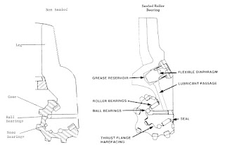
 

Figure 3-6a                   Figure 3-6b
There is, however, one serious drawback to the roller-ball-roller bearing
system. The primary cause of roller bearing failure is journal spalling,
which causes destruction of the rollers and the locking of the cone.
To remedy this, instead of the standard roller bearing assembly, the
“journal bearing” system utilizes solid metal bushings for direct cone to
journal contact. This offers a distinct mechanical advantage over roller
arrangements in that it presents a larger contact area at the load bearing
point. This distribution of the load eliminated the chief cause of roller
bearing assembly failure - spalling in the load portion of the bearing face.
Journal bearing systems in the tungsten carbide insert bits features a metal
bearing surface combined with a hardfaced journal and a lubricant.
Specialized seals and reliable pressure equalization systems keeps the
drilling fluid and formation contaminants out of bearings, and positively
seals the graphite-based lubricant inside the bearing. Precision fit of the
journal and cone distributes contact loading evenly throughout a nearperfect
arc. Bearing surfaces are finished to a carefully controlled surface
texture to ensure optimum lubrication.
The manufacturing of the journal bearing system consists of having the
journals either milled, grooved or pressed (depending on the bit company)
to accommodate the bushing. Then the bushings are inlaid on the journal.
Once the cone is fitted with teeth and gauge protection, the journal is then machine-pressed into the cone. To complete the seal between the cone and
the journal, special rings (seals) have been developed.
Seals
The first and still most popular seal is the radial seal (used mainly on the
sealed roller bearing bits). The radial seal is a circular steel spring encased
in rubber, which seals against the face of the shank and the face of the
cone. The newer “O” ring seal is considered the most effective seal. The
major problem confronting the “O” ring is tolerance, which must be precise
in order to maintain an effective seal.
An understanding of lubricants and lubricating systems is necessary for
successful drilling operations. The lubricating systems are essentially the
same, and are composed of an external equalizer located under the bit or on
back of the shanks, a grease reservoir with some sort of expandable
diaphragm to distribute the grease, and some sort of distribution system to
the bearings. In addition, there is a pressure relief valve to release any
trapped pressure, which might otherwise rupture the seals.
Pressure surges can be detrimental to these sealed systems. As pressure and
temperature increase, the viscosity of the lubricant increases. As a result,
the system cannot instantaneously compensate for abrupt changes in
pressure due to surges (going into the hole, making connections, etc.) and
small quantities of mud invade the system. With the close tolerance
necessary for effective sealing, mud solids can be damaging.
Adequate cleaning is even more important with sealed bearing bits. If
drilled cuttings are allowed to build up around the shirttail, seal damage
and premature bearing failure may result. Gauge protection is also
important to seal and bearing life, because seal damage can occur from
shirttail wear caused by inadequate gauge protection.
Any time a sealed bearing bit is rerun, the seals and shirttail should be
carefully checked for excessive wear or grooving.
To complete the journal-cone assembly, a positive seal is required to keep
drilling fluid out, while allowing the graphite lubricant in, which keeps the
bearings from overheating. The positive seal requires a relief valve to allow
escape of excess pressure, which can overload the seal and cause seal
failure.

Bit Technology- Cutting Structures - Gauge Protection

Gauge Protection


Protection of the gauge surface is vital to the effectiveness of any bit. The
gauge surfaces constantly ream the hole, and thus are subject to continuous
abrasive wear.
Applying tungsten carbide in a steel matrix through a welding process,
called “hardfacing”, provides the best resistance to this type of wear.
Gauge protection is improved as the amount of hardfaced surface area
increases.
The configuration of the gauge teeth determines the available surface area.
The “A” type teeth are standard for soft formation bits, resulting in
minimum gauge protection for drilling medium-hard formations. The “T”
type teeth provides the greatest amount of surface area for the application
of hard metal, and are used for abrasive formation bit types.
For work in very hard formations, a flat-top tungsten carbide insert is
pressed into the gauge surface for additional protection.
Gauge protection is specified in roller cone bits by adding a “G” to the
IADC code.

Bit Technology- Cutting Structures - Tungsten Carbide Cutting Structures

Tungsten Carbide Cutting Structures


Since most of the basic design features of the mill tooth cuttings structures
have been incorporated into insert bits, the main variations occur in insert
shape (Figure 3-5).


Figure 3-5: Tungsten Carbide Tooth Shapes
Historical shapes of milled teeth have built up a mystique about insert tooth
shape. Many people in the oil field thought that chisel shaped teeth
significantly affected the drill rate in all formations. This was because early
drilling practices used light bit weights, causing the relatively sharp chisel
shaped inserts to have a higher unit loading on the formation, hence faster
drill rates. When heavier bit weights are used, it tends to nullify the
advantage of the chisel shape. Even the steel milled teeth break down under
heavy weights. In fact, most bits drill 75% of the hole in a 1/2 to 3/4 dull
condition. With this in mind, many “blunt” insert tooth designs were made,
and seem to drill efficiently. Nowadays, most insert teeth have this blunt,
conical shape.

Bit Technology- Cutting Structures - Steel Tooth Cutting Structures


 Steel Tooth Cutting Structures


There are three basic design features incorporated in steel tooth cutting
structures, teeth spacing, tooth hardfacing, and tooth angle (Figure 3-4).
Using variations of these parameters, bits are separated into formation
types.


Soft Formation Cutting Structures
Teeth on this type of bit are few in number, widely spaced,
and placed in a few broad rows. They tend to be slender, with
small tooth angles (39° to 42°). They are dressed with hard
metal.
Medium Formation Cutting Structures
Teeth on medium formation bits are fairly numerous, with
moderate spacing and depth. The teeth are strong, and are a
compromise between hard and soft bits, with tooth angles of
43° to 46°. The inner rows as well as the gauge rows are
hardfaced.
Hard Formation Cutting Structures
There are many teeth on this type of bit. They are closely
spaced and are short and blunt. There are many narrow rows
with tooth angles of 46o to 50o. The inner rows have no
hardfacing, while the gauge row is hardfaced.

Bit Technology- Cutting Structures

Cutting Structures

In 1909, when roller cone bits were introduced into the oilfield, the drag bit
was replaced by the roller cone’s steel tooth cutting structure. These steel
(milled) teeth have undergone changes in height, number per cone, and
thickness, to accommodate the various types of formations.
When harder formations tended to “eat up” the steel teeth, a different
cutting structure was needed, and in 1949 the first insert bit was used.
Introduced by Hughes Tool Company and nicknamed the “The Chert Bit”,
it brought on-bottom drilling hours up from 5 hours to 30 hours or more.
Many of the design features in the milled tooth bits were incorporated into
insert bits.

Bit Technology- Circulation Systems - Jet Nozzles

Jet Nozzles


There are essentially three types of jet nozzles used in tri-cone bits.
Shrouded nozzle jets provide maximum protection against retainer ring
erosion, excessive turbulence or extended drilling periods. Standard jet
nozzles are easier to install and are recommended for situations where
erosion is not a problem. Air jet nozzles (see above) are used on bits
designated for drilling with air or gas.
Nozzle sizes play an important role in bit hydraulics. The benefits of the
correct selection include effective hole cleaning and cuttings removal,
faster drill rates and thus lower drilling costs.
Orifice sizes are stated in 1/32 inch increments, with the most common
being between 10/32 to 14/32 sizes. Directional bit jets are available in
sizes from 18/32 to 28/32.

Bit Technology- Circulation Systems - Air or Gas Circulation Bits

Air or Gas Circulation Bits


A third type of circulation medium is compressed air or gas, and can be
used with either regular or jet circulation bits. Bits manufactured for air or
gas circulation have special passageways from the bore of the bit to the
bearings, through which a portion of the air or gas is diverted to keep the
bearings cool and purged of dust or cuttings. From the special passageways
to the bearings, the air or gas passes through a number of strategically
located ports or holes in the bearing journal, flows through the bearing
structure and exhausts at the shirttail and gauge of the bit, to flow up the
annulus.  

Bit Technology- Circulation Systems - Regular Circulation Bits

Regular Circulation Bits


Regular circulation bits (Figure 3-3a), have one to three holes drilled in the
dome of the bit. Drilling fluid passes through the bore of the bit, through
the drilled holes, over the cutters, and then to the bottom of the hole, to
flush away the drill cuttings.

Bit Technology- Circulation Systems

Circulation Systems


The first hydraulic features incorporated into drilling tools dated back to
the original use of hollow drillpipe with direct circulation of drilling fluids.
As the first fishtail bits became popular, around the turn of the century,
circulation though water courses was used for the first time. The first
rolling cutter rock bits of 1909 introduced a central water course system
which directed fluid discharge towards the cutters.
In 1942, rock bits with jet nozzles were introduced to the oil industry. The
“jet bit” concept is considered to be the major hydraulic design
improvement in drill bits and remains state-of-the-art.
Further improvements in the circulation systems include extended nozzle
bits, seven to twelve nozzles in PDC bits, and the various water courses in
diamond bits.

Bit Technology- Interfitting Teeth and Cone Offset

Interfitting Teeth and Cone Offset


The idea of interfitting teeth (Figure 3-2a), makes it possible to have large bit parts, and allows the inner row of teeth to cut new formation on each rotation. Interfitting also offers some degree of self-cleaning. One result of this interfitting is that each of the three cones are different.

Cone offset (Figure 3-2b), is caused by the journal centerline not intersecting the bit centerline (or bit center of rotation). The distance that the journal centerline misses the bit centerline (measured perpendicular to the journal centerline at the center of rotation) is the offset.
The skew point is an arbitrary point along the journal centerline and is the angle formed by the offset, the centerline of the journal, and a line from the bit center to the skew point. The skew direction is always “positive”, or in the direction of rotation. This permits the tips of the teeth to “ream” the hole to full gauge. “Negative” skew would have the gauge face rubbing the hole wall, increasing gauge wear.

As with the journal angle, the offset will be different in each type of formation. In soft formation bits, the maximum offset (3o skew angle) is used to increase the gouging, scraping action. Medium formation bits add a limited offset (2o skew angle) to develop cutter action. While hard formation bits have no offset, to minimize gouging and scraping.

Bit Technology- Journal Angle

Journal Angle

One of the basic design fundamentals of rolling cutter rock bits is the journal angle. Though this angle may vary from one rock bit type to the next, in each bit the three journal angles are all identical.
The journal angle (Figure 3-1) is the angle at which the journal is mounted, relative to a horizontal plane. This mounting moves the cutting elements (cones) outside the support members. The journal angle also controls the cutter profile or pattern it drills, and it affects the amount of cutter action on
the bottom of the hole.

Journal angles are different for each “type” of formation:

Soft Formations

Journal angle (33o) - this allows a cutter profile which accentuates cutter action and permits greater tooth depth.

Medium Formations

Journal angle (34o to 36o), to decrease cutter action.

Hard Formations

Uses a large journal angle (39o), to minimize cutter action.

Bit Technology - Rolling Cutter Rock Bits

Rolling Cutter Rock Bits

The first successful rolling cutter rock bit was introduced into the oil field by Howard Hughes Sr. in 1909. Over the next fifteen years, the rolling cutter bit was used primarily in hard formation areas. This rolling cutter bit was a two-cone bit with cones that did not mesh, consequently, the bit had a tendency to “balled-up” in soft shales. The bit was redesigned with meshing teeth (self-cleaning) in the 1920s and in the early 1930’s, the tricone bit was introduced with cutters designed for hard and soft formations.
The primary drilling mechanism of the rolling cutter bits is intrusion, which means that the teeth are forced into the rock by the weight-on-bit, and pulled through the rock by the rotary action. For this reason, the cones and teeth of rolling cuttings rock bits are made from specially, case hardened steel.

One advantage of a rolling cutter bits is the three bearing design located around the journal of the bit. Heel bearings are roller bearings, which carry most of the load and receive most of the wear. Middle bearings are ball bearings, which hold the cone on the journal and resist thrust in either direction. The nose bearing consists of a special case hardened bushing pressed into the nose of the cone and a male piece, hard faced with a special material, to resist seizure and wear.

Although rock bits have been continually improved upon over the years, three developments remains outstanding: (1) the change in water course design and the development of the “jet” bit, (2) the introduction of the tungsten carbide insert cutting structure, and (3) the development of sealed journal bearings.

Bit Technology

Bit Technology

Upon completion of this chapter, you should be able to:

• Describe the components of roller cone and fixed cutter bits and understand why these variations are advantageous in certain situations.

• Determine the appropriate type of bit for a future bit run, given the previous bit performances.

• Describe the various types of fixed cuter bits.

• Explain why running procedures are different for fixed cutter bits.

Friday, 29 January 2016

Cement Additives

Cement Additives

Accelerators

An accelerator is a chemical additive used to speed up the normal rate of reaction between cement and water which shortens the thickening time of the cement, increase the early strength of cement, and saves time on the drilling rig. Cement slurries used opposite shallow, low-temperature formations require accelerators to shorten the time for "waiting-oncement". Most operators wait on cement to reach a minimum compressive strength of 500 psi before resuming drilling operations. When using accelerators, this strength can be developed in 4 hours. It is a good practice to use accelerators with basic cements because at temperatures below 100oF, neat cement may require 1 or 2 days to develop a 500 psicompressive strength.
Common accelerators are sodium metasilicate, sodium chloride, sea water, anhydrous calcium chloride, potassium chloride and gypsum.

Retarders

Neat cement slurries set quickly at a BHT greater than 110oF. A retarder is an additive used to increase the thickening time of cements. Besides extending the pumping time of cements, most retarders affect the viscosity to some degree. The governing factors for the use of retarders are temperature and depth. Common retarders are lignosulfonates, modified cellulose, organic acids, organic materials and borax.

Extenders

Extended cement slurries are used to reduce the hydrostatic pressure on weak formations and to decrease the cost of slurries. Extenders work by allowing the addition of more water to the slurry to lighten the mixture and to keep the solids from separating. These additives change the thickening times, compressive strengths and water loss. Common extenders are fly ash, bentonite, and diatomaceous earth. 

Pozzolans

Pozzolans are natural or artificial siliceous materials added to portland cement to reduce slurry density and viscosity. The material may be either a volcanic ash or a clay high in silica. The silica in the pozzolans combines with the free lime in dry cement, which means a soluble constituent is removed from the cement and the new cement is made more resistive. Common pozzolans are diatomaceous earth and fly ash.

Cementing Nomenclature

Cementing Nomenclature


Casing Centralizers


Centralizers assist in the removal of filter cake and displacement of drilling fluid by providing a more uniform flow path for the cement slurry. Close scrutiny of the mudlog and wireline logs will help in the placement of centralizers. Zones of increased permeability, doglegs and areas of key seating, should have centralizers placed around the casing

Wall Scratchers

These are most useful when running casing through a high fluid-loss drilling fluid. There are two types of wall scratchers, rotating scratchers used when the casing can be rotated (normally in vertical wells), and reciprocating scratchers used when the pipe is reciprocated (moved up and down). When these scratchers are placed in 15 to 20 foot intervals, overlapping cleaning occurs.

Wiper Plugs

Both top and bottom plugs are used during cementing operations. They are used to separate the various fluids from one another. The red bottom plug has a shallow top, is made of rubber, and has a hollow core. It is used ahead of the cement slurry to prevent cement/drilling fluid contamination and to clean the casing wall of filter cake. After the bottom plug comes into contact with the float valve, sufficient pressure (150 to 350 psi) causes the top diaphragm to rupture, allowing the cement slurry to
flow through it. The black top plug has a deep cup on its top and has a solid, molded rubber core. It is dropped after the cement slurry has been pumped, to prevent contamination with the displacement fluid. The top plug also signals the end of displacement by forming a seal on top of the bottom plug, causing a pressure increase.

Chemical Washes

Chemical washes are fluids containing surfactants and mud thinners, designed to thin and disperse the drilling fluid so that it can be removed from the casing and borehole. Washes are available for water-based and oil-based drilling fluids. They are designed to be used in turbulent flow conditions.

Spacers

Spacers are fluids of controlled viscosity, density and gel strength used to form a buffer between the cement and drilling fluid. They also help in the removal of drilling fluid during cementing.

jobs for Petroleum Engineers

HAYS Oil & Gas Dubai are recruiting for a 

Petroleum Engineer to be based in Dubai.  


Click on the link below to apply

https://m.hays.ae/job/JOB_1486252/apply/?jobSource=Linkedin&id=JOB_1486252 

jobs for "Rotating Equipment Engineers" Doha-Qatar

AH1524 - Fresh Graduate Engineers | WETICO


Job description

About Your Job:
Saudi Fresh Engineering graduate with good GPA and excellent Academic record. Fresh Engineering program concentrates on developing the core and leadership competencies of fresh graduate engineers in addition to enhancing their technical capabilities to help them utilize their best qualities to achieve optimum performance within their careers through a mentioned program for 2 years.

Desired Skills and Experience


Qualifications:
    • Bachelor degree in  Civil, Electrical and Mechanical Engineering.

Required Skills:
    • Problem Solving and analyzing skills
    • excellent communication skills.
    • Good user of Microsoft office Applications
click on the link below to apply

http://mostaqbaly.wetico.com/abunayyan/VacancyDetail.aspx?BusinessUnitID=932&VacancyID=104235&ChannelID=2396

ADCO Hiring Now - Abu Dhabi, UAE

Removal of the Drilling Fluid

Removal of the Drilling Fluid
For cementing operations to be successful, all annular spaces must be filled with cement, and the cement properly bonded to the previous casing and formation. In order for this to occur, all the drilling fluid must be displaced by the cement slurry. This is not always an easy matter, because there are several factors which affect the removal of the drilling fluid:

• washouts in the open hole, making it difficult to remove drilling fluid and filter cake
• crooked holes, making casing centralization difficult and drilling fluid not being removed from the low side
• poorly treated drilling fluids having high fluid losses Good drilling practices will not assure a good cement job, but they may help prevent a failure. The ideal drilling fluid for cementing operations should have:

• a low gel strength, with low PV and low YP
• a low density
• a low fluid loss
• a chemical make-up similar to the cement

Since these conditions are very seldom met, fluid washes and spacers are usually pumped ahead of the cement to remove as much drilling fluid as possible.

Cement Slurries

Cement Slurries
Water is added to dry cement to cause hydration and to make a pumpable
slurry. To be used correctly, several properties must be known: the yield per unit (cubic feet per sack), the amount of water required (gallons per sack), and its density (pounds per gallon).
Another important parameter is the cements “absolute volume”. This is the actual volume occupied by the material (the bulk volume includes the open spaces between the cement particles). For example, one sack (94 lbs) of cement has a bulk volume of 1 ft3, but if all the open spaces between the particles were removed, the absolute volume would be 0.478 ft3.
With dry materials (cement and additives), the absolute volume is used along with the water requirements to determine the slurry. For example, the absolute volume of one sack of cement (0.478 ft3) plus the water volume (5.18 gal/sk or 0.693 ft3) yields a slurry volume of 1.171 ft3 (0.478 +
0.693).
The absolute volume of the cement's components are normally found in tables, but may be calculated using:
For components that dissolve in water (sodium chloride, etc.), since they do not occupy as much space as the specific gravities would indicate, the absolute volume is determined from experimental data and placed. Slurry density is also determined. Since one sack of cement weighs 94 lbs, and 0.693 ft3 of water weighs 43.2 lbs, when mixed they yield 137.2 lbs of slurry. The slurry's density is then calculated by dividing slurry weight by slurry volume, 137.2 lbs / 1.171 ft3 equals 117.1 lbs/ft3 (15.7 ppg). Yield is converted to cubic feet per sack by using the constant 7.4805 (62.4
lbs/ft3 / 8.34 lbs/gal).
Fly ash, a synthetic pozzolan, is another major constituent of cements. A fly ash/cement mixture is designated as the ratio of fly ash to cement (expressed as 50:50 or 60:40, etc.) with the total always equaling 100. The first number is the percentage of fly ash (74 lbs/sack), the second number is cement (94 lbs/sack). A sack of fly ash and a sack of cement have the same absolute volume.
If other additives are included (gel, accelerators, retarders, etc.), the mixture is expressed as a percentage of weight of both cement and fly ash. The slurry is then expressed: 50:50:2% gel

Cementing Introduction

Cementing
Introduction

Oil well cementing is the process of mixing and displacing a slurry down the casing and up the annulus, behind the casing, where is allowed to “set”, thus bonding the casing to the formation. Some additional functions of cementing include:

• Protecting producing formations
• Providing support for the casing
• Protecting the casing from corrosion
• Sealing off troublesome zones
• Protecting the borehole in the event of problems

The main ingredient in most cements is “Portland” cement, a mixture of limestone and clay. This name comes from the solid mixture resembling the rocks quarried on the Isle of Portland, off the coast of England.

All cement is manufactured in essentially the same way. Calcareous and argillaceous materials (containing iron and aluminum oxides) are finely ground and mixed in correct proportions, either in a dry condition (dry processing) or with water (water processing). The mixture is then fed into the upper end of a sloping kiln at a uniform rate. The kiln is heated to temperatures from 2600o to 3000oF. As the mixture falls to the lower end, the mixture melts and chemical reactions occur between the raw materials.

When the mixture cools, it is called “clinker”. The clinker is then ground with a controlled amount of gypsum (1.5 to 3.0% by weight), to form portland cement.

The principle compounds resulting from the burning process are Tricalcium Silicate (C3S), Dicalcium Silicate (C2S), Tricalcium Aluminate(C3A), and Tetracalcium Aluminoferrite(C4AF). contains more information on the properties of these compounds. These materials are in an anhydrous form. When water is added, they convert to their hydrous form, which is then called a “cement slurry”.
The American Petroleum Institute (API) has established a classification system for the various types of cements, which must meet specified chemical and physical requirements. classifications and their applications to depths of 16,000 ft. (4880 m), under various temperature and pressure conditions.

Casing Couplings

Casing Couplings
Couplings are short pieces of casing used to connect the individual joints. They are normally made of the same grade of steel as the casing. Through their strength can be different than the casing. The API has specifications for four types of couplings.

• Short round threads and couplings (CSG)
• Long round threads and couplings (LCSG)
• Buttress threads and couplings (BCSG)
• Extremeline threads (XCSG)

The CSG and LCSG have the same basic thread design. The threads have a rounded shape, with eight threads per inch. These threads are generally referred to as API 8-round. The only difference between the two is that the LCSG has a longer thread run-out, which offers more strength for the connection. LCSG are very common couplings.

Buttress (BCSG) threads are more square, with five threads per inch. They are also longer couplings, with corresponding longer thread run-out. The XCSG (Extremeline) couplings are different from the other three connectors in that they are integral connectors, meaning the coupling has both box and pin ends.

Coupling threads are cut on a taper, causing stress to build up as the threads are made up. A loose connection can result in a leaking joint. An over-tight connection will result in galling, which again, will cause leaking. Proper make-up is monitored using torque make-up tables and the number of required turns.

A special thread compound (pipe dope) is used on casing couplings, each type of coupling having its own special compound. Many companies have their own couplings, in addition to the API standards, which offer additional features not available on the API couplings.

Casing properties

Casing properties are defined as:

• Yield Strength: The tensile stress required to produce a total elongation of 0.5% per unit length

• Collapse Strength: The maximum external pressure or force required to collapse the casing joint

• Burst Strength: The maximum internal pressure required to cause a casing joint to yield

Casing dimensions are specified by its outside diameter (OD) and nominal wall thickness. Normal wellsite conventions specify casing by its OD and weight per foot. As stated earlier, one should specify which weight one is referring to, though most often it is the nominal weight.

Casing Standards

Casing Standards

The American Petroleum Institute (API) has developed certain standards and specifications for oil-field related casing and tubing. One of the more common standards is weight per unit length. There are three “weights” used:

• Nominal Weight: Based on the theoretical calculated weight per foot for a 20 ft length of threaded and coupled casing joint.
• Plain End Weight: The weight of the joint of casing without the threads and couplings.
• Threaded and Coupled Weight: The weight of a casing joint with threads on both ends and a coupling at one end.

The Plain End Weight, and the Threaded and Coupled Weight are calculated using API formulas. These can be found in API Bulletin 5C3. API standards include three length ranges, which are:

• R-1: Joint length must be within the range of 16 to 25 feet, and 95% must have lengths greater than 18 feet
• R-2: Joint length must be within the range of 25 to 34 feet, and 95% must have lengths greater than 28 feet
• R-3: Joint length must be over 34 feet, and 95% must have lengths greater than 36 feet.

The API grade of casing denotes the steel properties of the casing. The grade has a letter, which designates the grade, and a number, which designates the minimum yield strength in thousands of psi.