In most fields, the new wells flow under it’s natural pressure until such time that the reservoir pressure is reduced to the point that the well can no longer flow under it’s natural pressure. The well now becomes a prime candidate for artificial lift.
There are various artificial lift mechanisms such as: gas lift, plunger lift, downhole electric or hydraulic pump, and rod pump. The selection of artificial lift depends on type of hydrocarbons, flow rate and the reservoir pressure. The design of lift systems also depends on the economics of the project.
Artificial lift is simply a method of adding energy to lift liquid to the surface of a well, and can be accomplished by any of the following means:
1. Gas Lift
- a) Continuous gas lift system
- b) Intermittent gas lift system
- c) Plunger lift system
2. Beam pumping or sucker rod pumping
3. Electric submersible pumping
4. Progressive cavity or screw type pumps particularly for heavy oil operations
5. Various special techniques e.g. hydraulic pumps, jet pumps etc.
Gas Lift
Gas lift systems can be used to effectively produce wells ranging from low productivity to high productivity. Gas lift systems are selected for artificial lift if a low cost, high pressure gas source is
readily available. In flowing wells, gas is produced along with the liquids. The gas comes out of solution and expands as the pressure is reduced as it flows up the tubing. The expanding gas assists in lightening the column of fluid, resulting in more inflow from the reservoir and also helps push the fluids out of the well.
In gas lift operations, high pressure gas is injected down the casing and enters the tubing at the bottom of the well through a pressurerated gas lift valve. As the gas rises the bubbles expand, increasing the velocity of the fluid and decreasing it’s density just as in flowing wells.
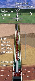
Figure 51 Gas Lifting
The applications of gas lift are:
i) To enable wells that will not flow naturally to produce
ii) To increase production rate in flowing wells
iii) To unload a well that will later flow naturally
iv) To remove or unload fluids from gas wellsand keep the gas wells unloaded (usually intermittent gas lift)
Continuous Gas lift
Under continuous gas lift, high pressure gas enters the tubing through gas lift valves continuously, maintaining a constant flowing bottomhole pressure. This action reduces the fluid gradient in the tubing and the well performs very similar to a natural flowing well. The gas lift valves can be either loaded or pressure balance release valves. The two different types of gas lift valves used in the industry are differential valves and bellows or charged valves.
The differential valves are normally open and when the pressure in the annulus is high enough, the valve closes. As the pressure in the tubing is less than the injected gas, the valve will not reopen until the tubing pressure has risen due to liquid loading or the injection pressure has decreased. The bellows pressure in the pressure charged bellows valve closes the valve. The valve opens when the annulus gas pressure acting on the area below the bellows plus the tubing pressure is greater than the bellows pressure. The valves are arranged in a string down the tubing with the bellows-pressure charge being less as the valve location is deeper, allowing the deeper valve to stay open when the valve above is closed.
Intermittent Gas Lift
Intermittent gas lift is used on wells that have low volumes of produced fluids. Intermitting is usually done using surface equipment. The gas lift supply is shut down for a predetermined period of time, allowing fluid inflow from the reservoir. The injection takes place again, removing fluids from the wellbore and then the next cycle begins. Some features of gas lift
i) Simple operation
ii) Very flexible – one gas lift design can handle a variety of changing well conditions
iii) Relatively low cost – both capital and operating
iv) Can be used in directional wells
v) Must have a high pressure gas supply
vi) Would not work on low API gravity crudes due to high specific gravity of the oil
vii) Requires a compressor, to recompress the gas for further gas lift use
Plunger Lift
Plunger lifting is an economical artificial lift alternative, especially in high gas oil ratio wells. A plunger is a “pipeline pig” that runs vertically in a well to remove liquids from a wellbore after the well is unable to produce fluids on it’s own drive mechanism. A plunger cycle consists of three stages:
Shut-in: A producing well is shut in to build casing pressure. This is needed to build the pressure to lift the plunger with the liquid column on top of the plunger.
Unloading: The tubing is opened, and stored casing pressure lifts the liquid column and plunger to the surface.
Afterflow: The well is allowed to flow while the plunger is at surface. During the afterflow period, the well keeps producing gas and fluids until the next shut-in period. At the end of the afterflow period, the well is shut in and the plunger falls. Plunger lift is used mainly in:
- High producing GOR wells
- Wells where scale, paraffins, wax foul up the tubing
- Gas wells that require liquid unloading
- Reducing liquid fall back (used along with intermittent gas lift)
Advantages of plunger lift
i) Low maintenance cost
ii) Increases the well’s own lifting efficiency
iii) Easy installation
iv) Reduces paraffin or hot oil expense for cleaning the deposits in the tubing as the moving plunger keeps the tubing clean
v) No external energy is required except for low gas oil ratio wells
vi) Slows well decline and extends well life
Beam Pumping
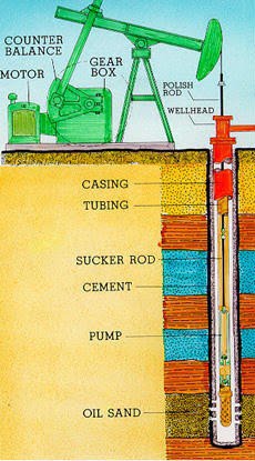
Figure 52 – Rod Pump
Beam Pumping is the most widely accepted artificial lift method. It utilizes a mechanical linkage to actuate a piston type bottomhole pump. The beam pump (or rod pump) is a plunger with a two valve arrangement. The standing valve is a one way valve in the bottom of the pump, which allows flow from the wellbore to the pump but stops reverse flow. The traveling valve is another one way valve that is attached to the rod string. As the plunger is lifted by the rod on the upstroke, the traveling valve is closed, forming a low pressure area beneath the plunger and drawing in reservoir fluid through the standing valve into the wellbore chamber.
At the end of the upstroke, the downstroke begins. When the bottom of the plunger (which contains the traveling valve) hits the surface of the liquid that has flowed into the pump, the traveling valve is forced open as the valve moves through the liquid and the standing valve is closed. The downstroke of the plunger forces the liquid in the pump up through the traveling valve, adding it to the tubing. The new fluid pushes all other fluid in the tubing up by the volume of the liquid in the pump. The most difficult task in beam pumping is keeping the rod string in operation without high maintenance costs, frequent servicing and excessive downtime. Problems associated with sucker rods result from:
i) Corrosion
ii) Carelessness in handling
iii) High pumping speeds
iv) Wide range of loads
v) Crooked hole
vi) Poor selection and string design
Sucker rod pumping is controlled by variable frequency drive and timer mechanism at the surface.
Electric Submersible Pump
A submersible pump is a pump which has a hermetically sealed motor close-coupled to the pump body. The whole assembly is submerged in the fluid to be pumped. The advantage of this type of pump is that it can provide a significant lifting force as it does not rely on external air pressure to lift the fluid.
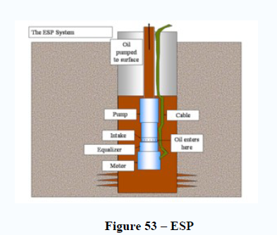
ESP systems are effective for pumping produced fluids to surface. A system of mechanical seals are used to prevent the fluid being pumped entering the motor and causing a short circuit. The pump can either be connected to a pipe, flexible hose or lowered down guide rails or wires so that the pump sits on a "ducks foot" coupling, thereby connecting it to the delivery pipework.
Submersible pumps are found in many applications, single stage pumps are used for drainage, sewage pumping, general industrial pumping and slurry pumping. Multiple stage submersible pumps are typically lowered down a borehole and used for water abstraction.
Submersible pumps are also used in oil wells. By increasing the pressure at the bottom of the well significantly, more oil can be produced from the well compared to natural production. This makes Electric Submersible Pumping (ESP) a form of "artificial lift" (as opposed to natural flow). New varieties of ESP can include a water/oil separator which permits the water to be reinjected into the reservoir without the need to lift it to the surface.
The ESP system consists of a number of components that turn a staged series of centrifugal pumps to increase the pressure of the well fluid and push it to the surface. The energy to turn the pump comes from a high-voltage (3 to 5 kV) alternating-current source to drive a special motor that can work at high temperatures of up to 300 °F (150 °C) and high pressures of up to 5000 lb/in² (34 MPa), from deep wells of up to 12000 feet (3.7 km) deep with high energy requirements of up to about 1000 horsepower (750 kW). ESPs have dramatically lower efficiencies with significant fractions of gas, greater than about 10% volume at the pump intake. Given their high rotational speed of up to 4000 rpm (67 Hz) and tight clearances, they are not very tolerant of solids such as sand.
Progressive Cavity Pump
Progressing Cavity Pumping (PCP) Systems typically consist of a surface drive, drive string and downhole PC pump. The PC pump is comprised of a single helical-shaped rotor that turns inside a double helical elastomer-lined stator. The stator is attached to the production tubing string and remains stationary during pumping. In most cases the rotor is attached to a sucker rod string which is
suspended and rotated by the surface drive.
As the rotor turns eccentrically in the stator, a series of sealed cavities form and progress from the inlet to the discharge end of the pump. The result is a non-pulsating positive displacement flow
with a discharge rate proportional to the size of the cavity, rotational speed of the rotor and the differential pressure across the pump.
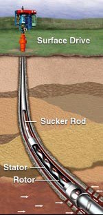
Figure 54 – PCP
PCP System Applications
· Sand-laden heavy crude oil and bitumen
· Medium crude oil with limits on H2S and CO2
· Light sweet crude oil with limits on aromatic content
· High water cuts
· Dewatering gas wells such as coalbed methane projects
· Mature waterfloods
· Visual and/or height sensitive areas
· All type wells, including horizontal, slant, directional and vertical reservoirs
There are two basic elements that make up the downhole Progressing Cavity (PC) Pump – a single helical alloy-steel rotor connected to a rod string and a double helical elastomer-lined stator attached to the tubing string. Using the latest manufacturing technology, rotors are kept to tight tolerances and
treated with chemical and abrasion-resistance coating, typically hard chrome. Stators are comprised of a steel tube with an elastomer molded inside to provide the internal geometry. Each combination of rotor/stator is matched to downhole conditions to provide highly efficient operation and optimum production enhancement.
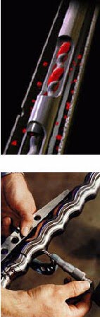
Figure 55 – Rotor
No comments:
Post a Comment