There are three basic types of well completion:
1. Conventional Single zone Completion
2. Conventional Multiple zone Completion
3. Tubingless Completion
Conventional Single Zone Completion
Open Hole Completion
This is the simplest of all completion types, where casing is run and cemented just above the producing zone. The pay section is drilled with a non-damaging fluid. Open hole completions can be barefoot, where tubing is run and a packer is set in the casing above the open hole the well put on production. Another option is to run a gravel pack liner or screen and gravel pack the open interval. This is known as an Open Hole Gravel Pack completion. The open hole can also be widened using an under-reamer and then gravel packed. Productivity of open hole gravel packs is higher than the cased hole gravel packs because the hydrocarbon flows into a larger tube.
Some features of open hole gravel pack completions:
i) It is run in consolidated sandstone or carbonate reservoirs
ii) Perforating expense is eliminated
iii) It provides good sand control
iv) The entire pay section is produced
v) It can easily be converted to cased hole completion
vi) It is difficult to selectively stimulate using acid or fracturing
vii) The casing is set “in the dark” before the pay section is drilled
viii) It is difficult to eliminate water or gas production
Single Zone Cased Hole Completion
In this completion, casing is run and cemented to the bottom of the pay zone. In some cases the well is drilled and cased beyond the pay zone, leaving a “rat hole” below the perforated zone. The size of the casing is determined based on the expected rate of production of the well. The thickness of the casing is determined based on both the external and the internal pressures the casing must withstand. These are called collapse and burst pressures. Single zone cased hole completions may be with gravel packed screens or liners for sand control.
Some features of open hole gravel pack completions:
i) It is easier to selectively stimulate using acid or fracturing
ii) Different intervals can be stimulated selectively
iii) Multiple completion is possible
iv) The well can be easily deepened
v) Perforating cost can be high
vi) Various sand control techniques can be utilized
Conventional Multiple Completion
Conventional Multiple Completion is utilized when there are two zones in a well that contain significantly different reservoir pressures. If both are produced together and allowed to mix, some production from the higher pressure zone will preferably flow into the lower pressure zone, especially when the well is shut in. Thus it is necessary to isolate production from both zones.
This is achieved by placing a dual packer between both zones and allowing flow up two different tubing strings (see diagram).

Tubingless Completion
In this type of completion the casing is small and no inner tubing is run in the hole. Tubingless completions can be single zone or multiple zone. The zones are perforated using “orienting guns” which utilize magnetism to orient the guns away from the other casing strings in the hole, while perforating the selected zone.
Tubing
Tubing is set inside the casing to transmit fluids from downhole to surface, with minimal pressure drop. Another factor is gas expansion in the tubing, which assists in the lifting of the liquids to the surface. To achieve this, tubing is usually small in diameter e.g 2 3/8”, 2 7/8”, 3 ½”. In choosing the optimum size of tubing the following is considered:
i) The desired flow rate
ii) Gas and liquid ratio for liquid loading in the tubing
iii) Possible artificial lift method to be employed.
iv) Special requirements for completion e.g. sand control
Packers
Packers are set in the wellbore to provide a seal between the tubing and casing.They also serve an anchors/hangers for the production tubing.A packer may be classified by the way it is set: hydraulic or mechanical set, by the way it is run: wireline or tubing, or by whether permanent or temporary.
Packers are run for:
i) Casing protection from pressure or fluid in the tubing
ii) Separation of zones
iii) Subsurface pressure and fluid control for safety
iv) Artificial lift support equipment
Wellheads
Wellheads are the connection points for the tubing and the surface flow lines as well as being the surface control point in all wells. The selection of the wellhead is based on the pressure, temperature and corrosivity of the produced fluids. Both the casing and tubing strings are landed in the wellhead. The casing also acts as a conduit allowing for all types of workover operations. Wellheads plays a major role in preventing oncontrolled flow from downhole, through it’s configuration of valves.
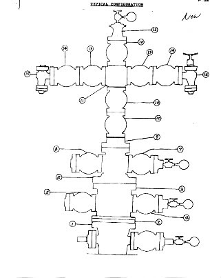
A SECTION
Casing head 13 5/8" 5M X l3 3/8" SOW w/2 1/16" 5M F.O. & 6" L.P. w/hold down screws; Valve WKM 2 1/16" 5M RJ MM T-21; 2 Flanges threaded 2 1/16" 5M X 2" LP; l-Bull Plug 2" LP plain; 1-Bull Plug 2" LP X 1/2" NPT.
B SECTION
2. AP Flange Packoff TS-5 13 5/8" 5M X 11" 10M W/9 5/8" "P" Seals.
3. AP Casing Spool 11" 10M X 11" 15M "SF" w/1 13/16" 15H F.O. and hold down screws for wear bushing and 2-9 5/8" 'P" seals RC-22 w/K-Monel Hd. Screws.
4. Valve WKH 1 13/16" 15M 6BX MM T-22 w/test flange 1 13/16" 15N X 1 1/8" autoclave.
5. Valve WKM 1 13/16" 15M 6BX MM T-22 w/weld neck flange, C SECTION
6. Tubing head 11" 15M X 7 1/16" 20M w/1 13/16' 20M outlets. RC22 W/K-Monel hold down Screws,
7. Valve - WKM 1 13/16" 20M 6BX MN T-26 w/test flange 1 13/16" 20M X 1 1/8" S.S.
8. Valve - WKM 1 13/16" 20M 6BX MN T-26 w/weld neck flange. UPPER SECTION
9. AP Flange Adp. Spool 7 1/16r X 2 9/16" 20H w/"P'" seals to accept metal to metal hanger S.S., and UEMM Tbg. Hanger w/metal to metal seals; Nom. 6" X 3 1/2" 15.80# PH6 CB L X S 2 1/2" BPV 17.4 PH S.S.
10. Valve WKM 2 9/16" 20M 6BX MM T-26.
11. AP Cross Stud. 2 9/16" 20M Run X 1 13/16" 20M out. S.S,
12. AP Top Adapter 2 9/16" 20M S,S. w/2 7/8" Lift Threads. BP Tapped 1 1/8" 12 NF,
13. Valve WKM 1 13/16" 2OM 6OX MM T-25.
14. Valve WKM 1 13/16- 20M T-26 w/.s-600 actuator and bonnet kit,
15. Pos. Choke - T[[C 1 13/16" 20M FXF S.S, w/weld neck 1 13/16" 20M RC22 flange,
16. Adj. Choke - THC 1 13/16- 2OM FXF S.S. w/weld neck I 13/16" 20M RC22 flange.
Perforating
Perforations are hole through casing to permit entry of fluids. The perforations must be placed opposite the productive zones and are designed to penetrate both the casing and the cement placed behind it, thus allowing communication between the permeable part of the reservoir and the borehole.
The “shaped charge” or “jet charge” is the most commonly used perforating technique used today. This mechanism produces a hole in the casing by propagating a pressure wave front from the surface of the metal liner in the charge, through the port or scalloped wall of the gun and then through the casing and cement into the formation. The metal liner of the charge deforms under high pressure and provides mass, which makes the charge more efficient.
In order to achieve this, a chain reaction is triggered from an electrically-fired detonator, which detonated the primacord, booster charge and the main charge. Usually four (4) one half inch (1/ inch) diameter holes per foot are required, except in gravel packing operations where 4 to 8 three-quarter inch (3/4 inch) holes are shot. The higher density larger holes accommodate transport of gravel through the perforations with less pressure drop across them.
The three (3) typical perforating guns used for perforating wells are: casing, through tubing and tubing conveyed guns.
Casing Gun Perforating
The casing guns are hollow steel carrier guns run on wireline. This gun is run without the tubing in the hole and requires a wireline lubricator connected on top of a shooting valve. The tubing is run after the guns are fired and retrieved from the borehole. An electric current, sent down the wireline to a detonator, fires the guns. This type of gun is used for overbalance perforating. “Overbalance” occurs when the hydrostatic head, due to the density and weight of the perforating fluid, is greater than the reservoir pressure. Casing gun perforating is cheaper than the other two types and is used for low pressure, low rate wells.
Through tubing perforating
The through tubing guns contain charges that are screwed into a thin metal strip that can pass through the tubing. The tubing is run in the hole , packer set and well head installed. A wireline lubricator is installed on top of the wellhead. A grease injector head is installed on the lubricator since this type of perforating can withstand some pressure from the well. The firing mechanism is the same as casing gun perforating.
Multiple runs have to be made since the length of the perforating gun, and hence the number of charges per run, are restricted by the length of the lubricator. The advantage of this type of perforating is that the well can be flowed as soon as the last run is completed, and it is not as expensive as tubing conveyed perforating.
Tubing Conveyed Perforating
Tubing Conveyed Perforating or TCP as it is more popularly known is the most expensive of the three and is used for high production rate wells. The perforating guns are run on hollow steel and attached at the end of the tubing. The tubing is run in the hole, packer set and wellhead installed. The guns are fired either by tubing pressure or by dropping a steel bar in the tubing, which sets off the detonator on impact. Sometimes,\ especially in deep wells, the drop bar method is utilized as a back-up mechanism. This type of perforating is done underbalance (the hydrostatic head is less than the reservoir pressure). This results in gun debris being flowed back immediately upon perforating as the wellhead sees an immediate pressure and the well can be produced and cleaned up immediately.
No comments:
Post a Comment