Depending upon the remoteness of the drill site and its access, equipment may be transported to the site by truck, helicopter or barge. Some rigs are built on ships or barges for work on inland water where there is no foundation to support a rig (as in marshes or lakes). Once the equipment is at the site, the rig is set up. Here are the major systems of a land oil rig:
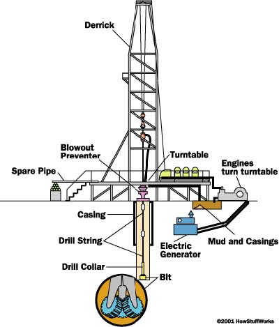
Figure 45 – Anatomy of an oil rig
· Power system
large diesel engines burn diesel fuel to provide the main source of power
electrical generators are powered by the diesel engines to provide electrical power
· Mechanical system - driven by electric motors
hoisting system - used for lifting heavy loads; consists of a mechanical winch (drawworks) with a large steel cable spool, a block and tach\kle pulley and a receiving storage reel for the cable
turntable - part of the drilling apparatus
· Rotating equipment - used for rotary drilling
swivel - large handle that holds the weight of the drill string; allows the string to rotate and makes a pressure-tight seal on the hole
kelly - four- or six-sided pipe that transfers rotary motion to the turntable and drill string
turntable or rotary table - drives the rotating motion using power from electric motors
drill string - consists of drill pipe (connected sections of about 30 ft / 10 m) and drill collars (larger diameter, heavier pipe that fits around the drill pipe and places weight on the drill bit)
drill bit(s) - end of the drill that actually cuts up the rock; comes in many shapes and materials (tungsten carbide steel, diamond) that are specialized for various drilling tasks and rock formations
· Casing - large-diameter concrete pipe that lines the drill hole, prevents the hole from collapsing, and allows drilling mud to circulate
· Mud Circulation system - pumps drilling mud (mixture of water, clay, weighting material and chemicals, used to lift rock cuttings from the drill bit to the surface) under pressure through the kelly, rotary table, drill pipes and drill collars
pump - sucks mud from the mud pits and pumps it to the drilling apparatus
pipes and hoses - connects pump to drilling apparatus
mud-return line - returns mud from hole
shale shaker - shaker/sieve that separates rock cuttings from the mud
shale slide - conveys cuttings to the reserve pit
reserve pit - collects rock cuttings separated from the mud
mud pits - where drilling mud is mixed and recycled
mud-mixing hopper - where new mud is mixed and then sent to the mud pits
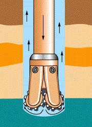
Figure 46 Mud circulation in the hole

Figure 47 - Drill-mud circulation system
· lift soil/rock cuttings from the bottom of the borehole and carry them to a settling pit;
· allow cuttings to drop out in the mud pit so that they are not re-circulated (influenced by mud thickness, flow rate in the settling pits and shape/size of the pits);
· prevent cuttings from rapidly settling while another length of drill pipe is being added (if cuttings drop too fast, they can build-up on top of the bit and seize it in the hole);
· create a film of small particles on the borehole wall to prevent caving and to ensure that the upward-flowing stream of drilling fluid does not erode the adjacent formation;
· seal the borehole wall to reduce fluid loss (minimizing volumes of drilling fluid is especially important in dry areas where water must be carried from far away); · cool and clean the drill bit; and lubricate the bit, bearings, mud pump and drill pipe
· Derrick - support structure that holds the drilling apparatus; tall enough to allow new sections of drill pipe to be added to the drilling apparatus as drilling progresses
Blowout prevention
A blowout occurs when there is loss of control of downhole reservoir fluid pressures., when the hydrostatic pressure due to the column of mud in the hole is less than the reservoir pressure. When a higher than normal reservoir pressure is drilled into, it may be necessary to activate the blowout prevention system (BOP stack) to provide time to kill the well. The BOP stack is usually a combination of different types of blowout preventers.
· Blowout preventer - high-pressure valves (located under the land rig or on the sea floor) that seal the high-pressure drill lines and relieve pressure when necessary to prevent a blowout (uncontrolled gush of gas or oil to the surface, often associated with fire)
The BOP stack is usually located below the rotary table. A typical BOP stack consists of three (3) blowout preventers is shown below:
ii) Blind Rams (middle)
iii) Pipe Rams (bottom)
No comments:
Post a Comment